
Automatic zincification device and control method thereof

A driving device and automatic technology, applied in coating, metal material coating process, hot-dip galvanizing process, etc., can solve the problem of insufficient precision in improving the stability of zinc addition, poor precision in zinc addition and temperature control, and harsh working environment And other problems, to achieve the effect of fully automatic control, improve precision, and avoid splashing of zinc liquid

Inactive Publication Date: 2013-06-19
BAOSHAN IRON & STEEL CO LTD
View PDF3 Cites 4 Cited by
  • Summary
  • Abstract
  • Description
  • Claims
  • Application Information

AI Technical Summary

Problems solved by technology

[0002] The hot-dip galvanizing unit in the cold rolling process is equipped with a zinc pot for galvanizing. Due to the continuous consumption of zinc liquid during the production process, it is necessary to supplement zinc to the zinc pot. The existing zinc supplement method is to manually add zinc ingots. However, the amount of zinc added and the accuracy of temperature control by manual operation will be poor, and because the temperature of the zinc liquid in the zinc pot reaches nearly 500°C, and the upper part of the zinc pot is equipped with an air knife for purging to control the thickness of the zinc layer, the working environment in this area is harsh , more sources of danger
[0003] The publication date is December 3, 2008, the publication number is CN201158695, and the Chinese patent document titled "A Zinc Adding Ingot Guiding Device" describes a tilting zinc adding chute, and the zinc ingots fixed in the chute Gradually integrate into the zinc pot by changing the tilting degree. Compared with manual direct hoisting and adding, this method reduces the risk, but it is not enough for the improvement of the stability of zinc addition and the accuracy of zinc liquid level and temperature control.
And because it is closer to the zinc pot, it fails to fundamentally solve the source of danger of poor working conditions

Method used


Image

  • Automatic zincification device and control method thereof
  • Automatic zincification device and control method thereof
  • Automatic zincification device and control method thereof

Examples


Embodiment Construction

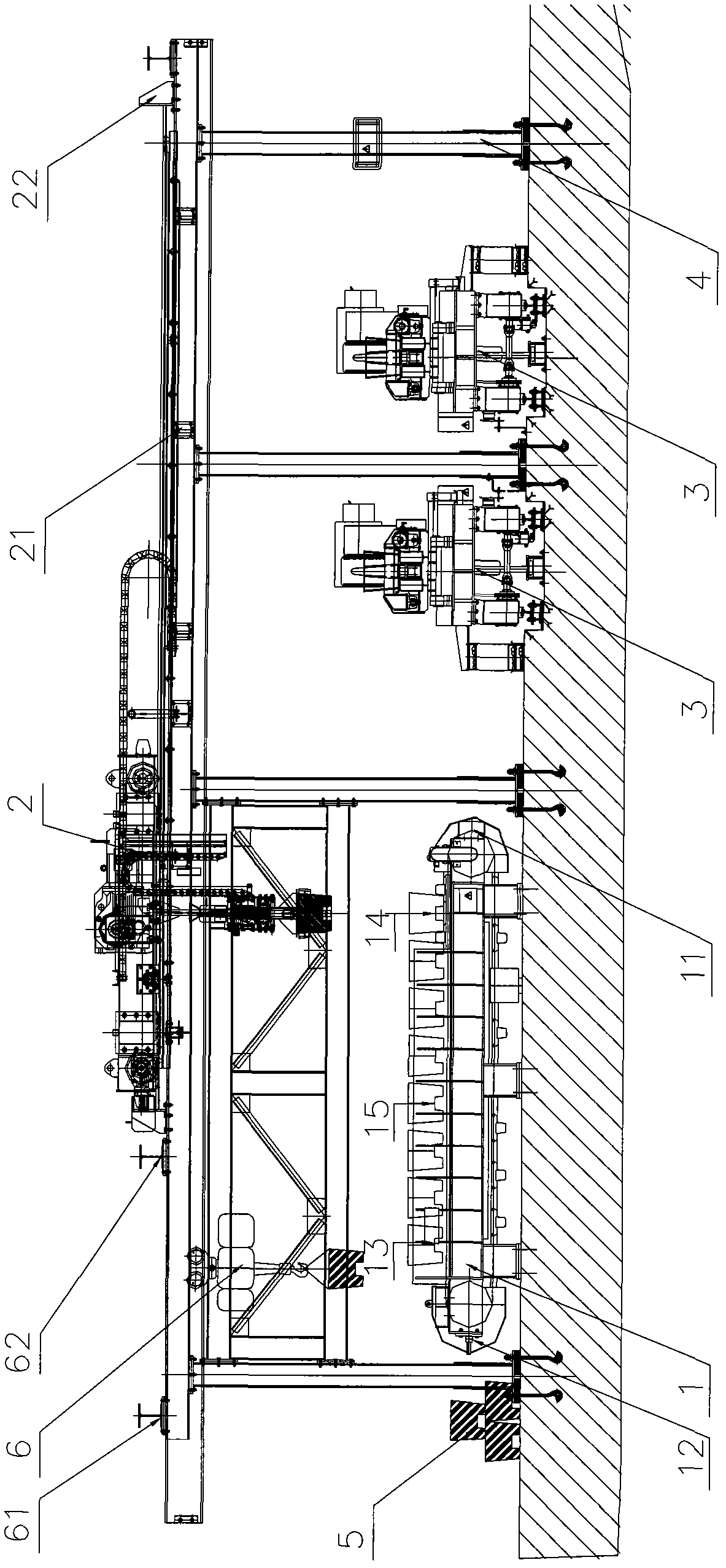
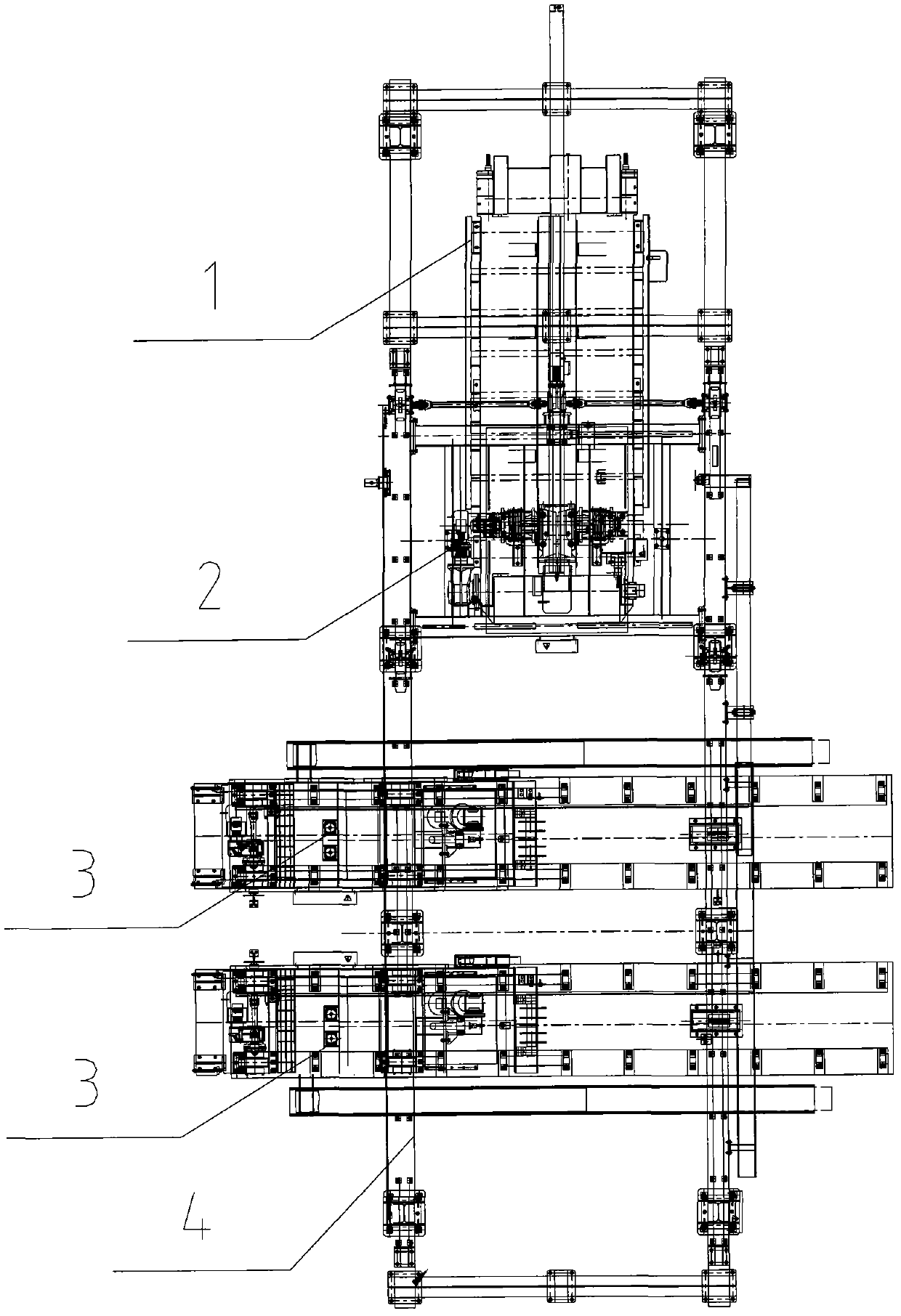
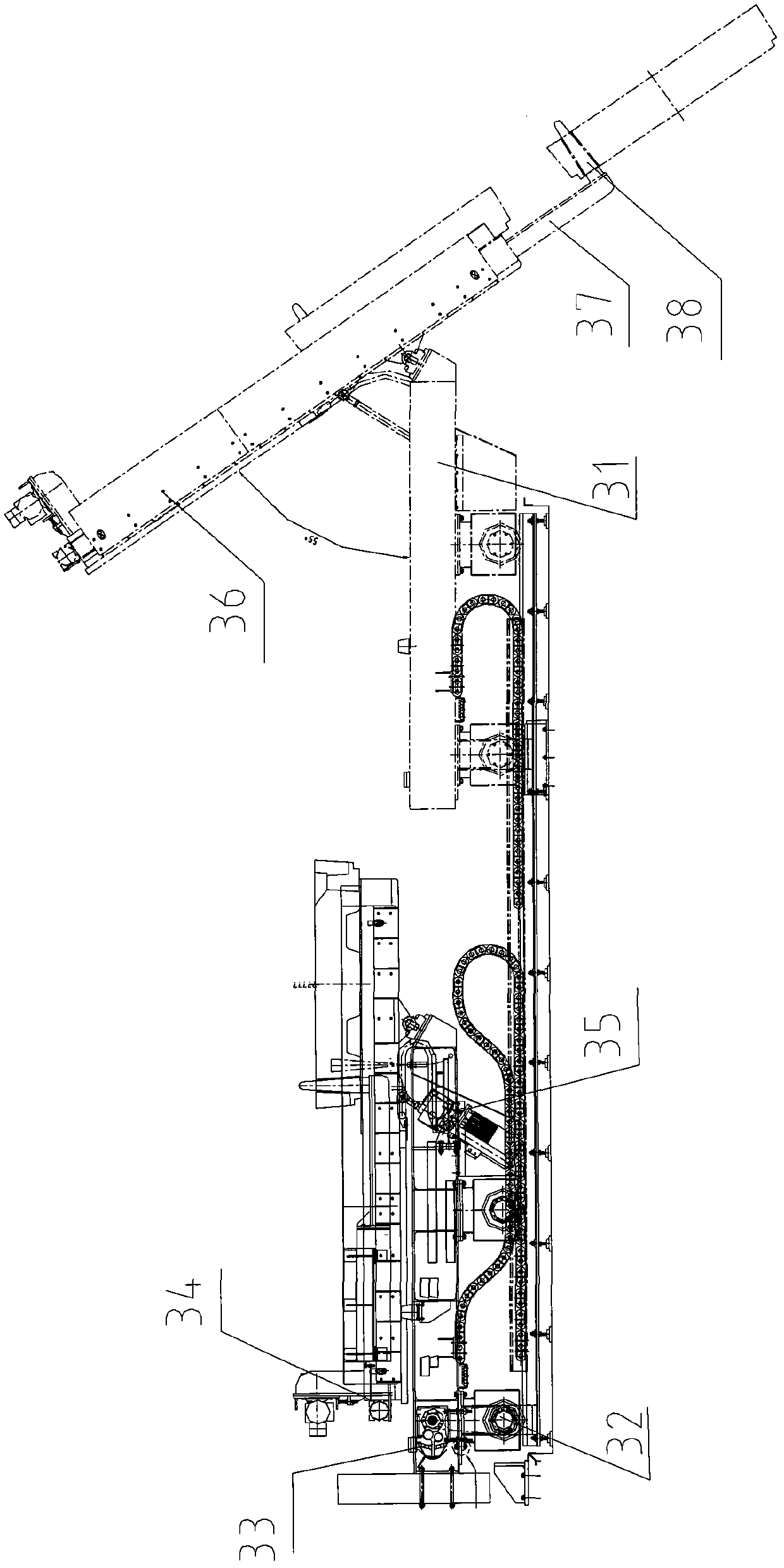
[0047] like figure 1 and figure 2As shown, the automatic zinc adding device includes: the control PLC as the general control element of the whole automatic zinc adding device; the support 4 includes several columns and horizontally arranged tracks; the manipulator device 2 is located on the horizontal track of the support 4, and the manipulator Device 2 includes: a walking trolley and a manipulator fixedly connected thereto, the walking trolley is electrically connected to the control PLC, and accepts the control of the control PLC to walk along a horizontal track, and the walking limit position of the walking trolley is determined by the first limit switch 21 and the second limit switch respectively. The switch 22 detects and transmits to the control PLC; the manipulator is electrically connected to the control PLC, accepts the control of the control PLC to grip the zinc ingot, and moves vertically up and down. The upper sensor and the lower sensor on the manipulator device ...


PUM


Abstract

The invention discloses an automatic zincification device which comprises a control PLC (Programmable Logic Controller), a bracket, a manipulator device, a conveyer and at least one zincification trolley, wherein the manipulator device is arranged on the bracket and is connected with the control PLC; the conveyer is arranged below the front part of the bracket along the length direction of the bracket and is connected with the control PLC; the zincification trolley is arranged below the rear part of the bracket and moves along a zincification trolley operating track; the zincification trolleyoperating track is vertical to the bracket; and the zincification trolley is connected with the control PLC. Correspondingly, the invention also provides a control method of the automatic zincification device. By the automatic zincification device and the control method thereof, the full automation of the zincification process can be realized.

Description

technical field [0001] The invention relates to a transportation device and a control method thereof, in particular to an automatic zinc adding device and a control method thereof. Background technique [0002] The hot-dip galvanizing unit in the cold rolling process is equipped with a zinc pot for galvanizing. Due to the continuous consumption of zinc liquid during the production process, it is necessary to supplement zinc to the zinc pot. The existing zinc supplement method is to manually add zinc ingots. However, the amount of zinc added and the accuracy of temperature control by manual operation will be poor, and because the temperature of the zinc liquid in the zinc pot reaches nearly 500°C, and the upper part of the zinc pot is equipped with an air knife for purging to control the thickness of the zinc layer, the working environment in this area is harsh , more sources of danger. [0003] The publication date is December 3, 2008, the publication number is CN201158695,...

Claims


Application Information

Patent Timeline
Patent Type & Authority Patents(China)
IPC IPC(8): C23C2/06
Inventor 叶冬柏
Owner BAOSHAN IRON & STEEL CO LTD
Learn More