Magnetorheological valve
A magnetorheological valve and flow plate technology, applied in the field of magnetorheological valves, can solve the problems of restricting the development and application of magnetorheological valves, narrow pressure adjustment range, small damping force of magnetorheological valves, etc., so as to improve the utilization of magnetic energy. efficiency, improve the utilization rate, and reduce the effect of magnetic flux leakage
- Summary
- Abstract
- Description
- Claims
- Application Information
AI Technical Summary
Problems solved by technology
Method used
Image

Examples
Embodiment 1
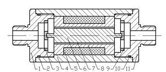
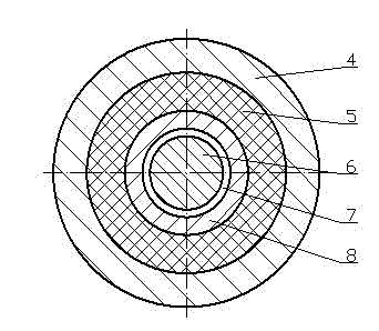
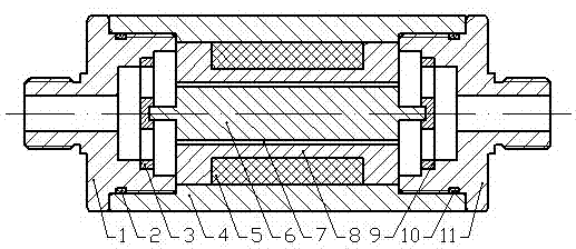
[0017] Embodiment 1: as Figure 1-2 As shown, a magnetorheological valve includes a left valve joint 1, a left sealing ring 2, a left support flow plate 3, a valve body 4, a coil 5, a valve core 6, a working gap 7, an iron core 8, and a right support flow plate Flow plate 9, right sealing ring 10, right valve joint 11. The coil 5 is wound on the iron core 8 , the iron core 8 is loaded into the valve body 4 through a transition fit, the valve core 6 is loaded into the hole of the iron core 8 , and a working gap 7 is formed between the valve core 6 and the iron core 8 . The working gap 7 has a width of 0.1 mm and a length of 8 mm. The two ends of the spool 6 are respectively supported and axially fixed by the left support flow plate 3 and the right support flow plate 9, and the left support flow plate 3 and the right support flow plate 9 are respectively installed into the left valve joint 1 and the Among the right valve joints 11, the left valve joint 1 and the right valve jo...
Embodiment 2
[0018] Embodiment 2: as Figure 1-2 As shown, a magnetorheological valve includes a left valve joint 1, a left sealing ring 2, a left support flow plate 3, a valve body 4, a coil 5, a valve core 6, a working gap 7, an iron core 8, and a right support flow plate Flow plate 9, right sealing ring 10, right valve joint 11. The coil 5 is wound on the iron core 8 , the iron core 8 is loaded into the valve body 4 through a transition fit, the valve core 6 is loaded into the hole of the iron core 8 , and a working gap 7 is formed between the valve core 6 and the iron core 8 . The working gap 7 has a width of 3 mm and a length of 200 mm. The two ends of the spool 6 are respectively supported and axially fixed by the left support flow plate 3 and the right support flow plate 9, and the left support flow plate 3 and the right support flow plate 9 are respectively installed into the left valve joint 1 and the Among the right valve joints 11, the left valve joint 1 and the right valve jo...
Embodiment 3
[0019] Embodiment 3: as Figure 1-2 As shown, a magnetorheological valve includes a left valve joint 1, a left sealing ring 2, a left support flow plate 3, a valve body 4, a coil 5, a valve core 6, a working gap 7, an iron core 8, and a right support flow plate Flow plate 9, right sealing ring 10, right valve joint 11. The coil 5 is wound on the iron core 8 , the iron core 8 is loaded into the valve body 4 through a transition fit, the valve core 6 is loaded into the hole of the iron core 8 , and a working gap 7 is formed between the valve core 6 and the iron core 8 . The working gap 7 has a width of 1.3 mm and a length of 28 mm. The two ends of the spool 6 are respectively supported and axially fixed by the left support flow plate 3 and the right support flow plate 9, and the left support flow plate 3 and the right support flow plate 9 are respectively installed into the left valve joint 1 and the Among the right valve joints 11, the left valve joint 1 and the right valve j...
PUM
 Abstract
Description
Claims
Application Information
 - R&D
- Intellectual Property
- Life Sciences
- Materials
- Tech Scout
- Unparalleled Data Quality
- Higher Quality Content
- 60% Fewer Hallucinations
Browse by: Latest US Patents, China's latest patents, Technical Efficacy Thesaurus, Application Domain, Technology Topic, Popular Technical Reports.
© 2025 PatSnap. All rights reserved.Legal|Privacy policy|Modern Slavery Act Transparency Statement|Sitemap|About US| Contact US: help@patsnap.com