Laminate type ceramic electronic component and manufacturing method therefor

一种电子部件、制造方法的技术,应用在固定电容的零部件、叠层电容器、固定电容器电极等方向,能够解决层叠型陶瓷电子部件可靠性降低、部件主体易产生间隙、镀膜产生裂纹等问题,达到固定力优良、固定力或者密封性提高、耐湿可靠性提高的效果

一种电子部件、制造方法的技术,应用在固定电容的零部件、叠层电容器、固定电容器电极等方向,能够解决层叠型陶瓷电子部件可靠性降低、部件主体易产生间隙、镀膜产生裂纹等问题,达到固定力优良、固定力或者密封性提高、耐湿可靠性提高的效果

CN102376450AActive Publication Date: 2012-03-14MURATA MFG CO LTD

Image

  • Laminate type ceramic electronic component and manufacturing method therefor
  • Laminate type ceramic electronic component and manufacturing method therefor
  • Laminate type ceramic electronic component and manufacturing method therefor

Examples


Embodiment Construction

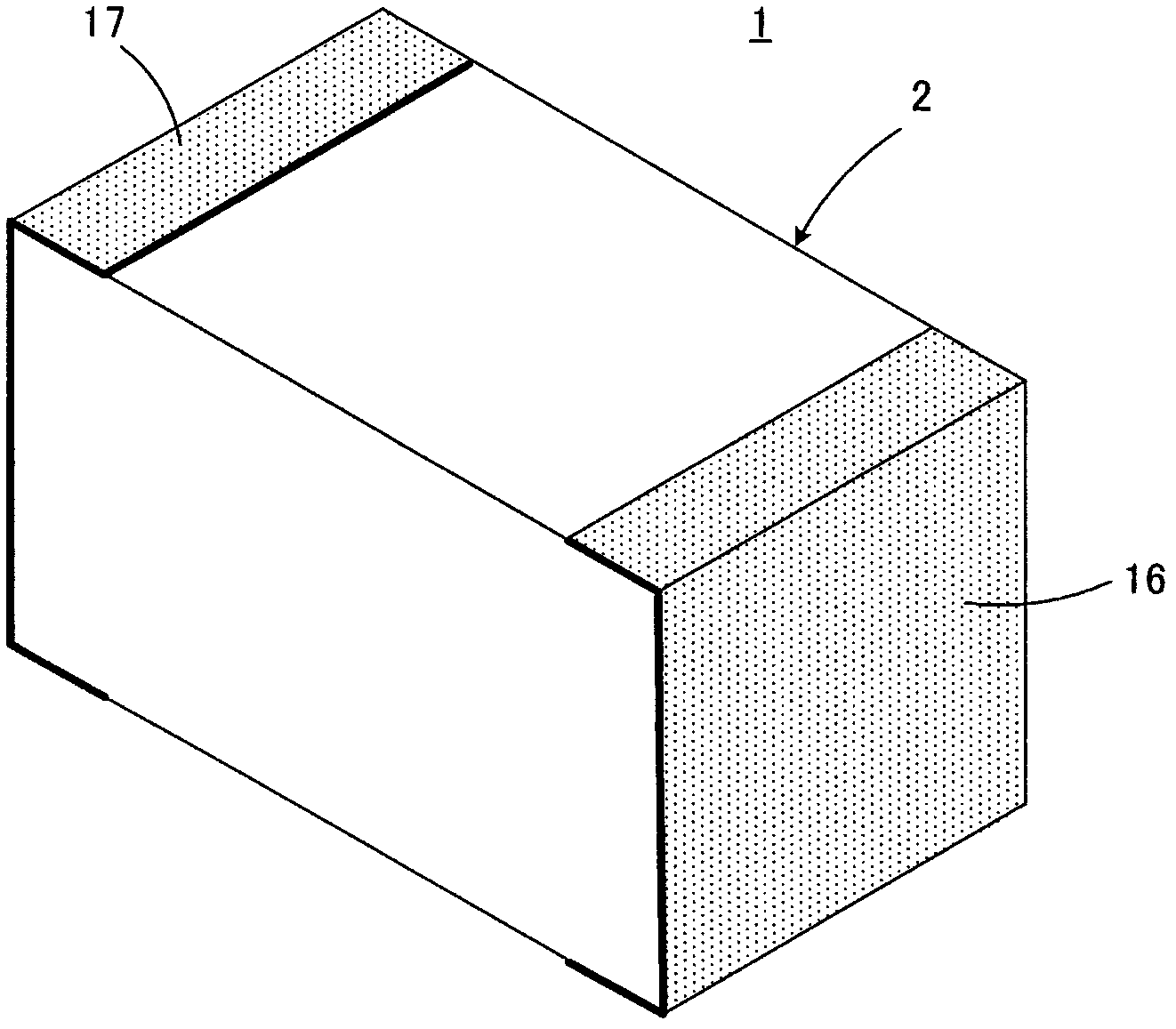
[0041] For the structure of a multilayer ceramic capacitor as a multilayer ceramic electronic component according to one embodiment of the present invention, refer to Figure 1 to Figure 4 And it demonstrates by its manufacturing method.

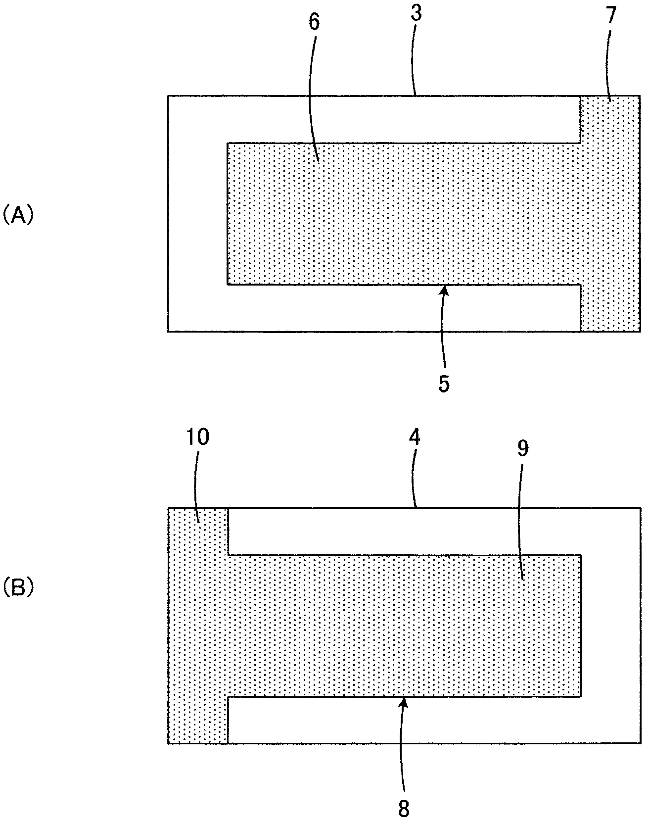
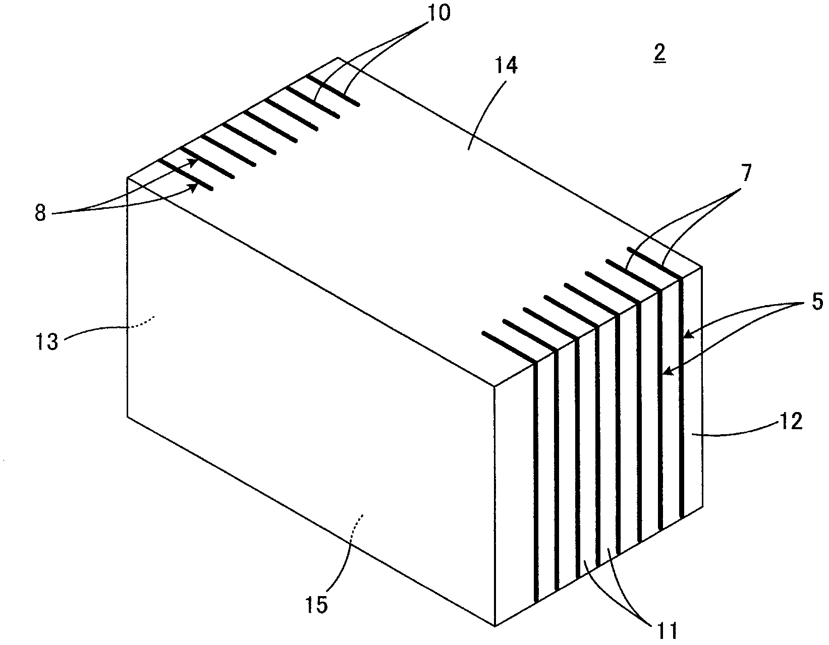
[0042] for manufacturing image 3 Multilayer ceramic capacitors shown in 1, prepare the figure 2 Part body 2 shown. Additionally, in order to get figure 2 The parts shown in Body 2, prepare the figure 1 Two kinds of ceramic green sheets 3 and 4 are shown.

[0043] exist figure 1 The first internal electrodes 5 are formed on the ceramic green sheet 3 shown in (A). The first internal electrode 5 has a capacitance forming portion 6 and a lead portion 7 constituting its main parts. The lead-out portion 7 extends so as to reach one short side of the ceramic green sheet 3 and a part of two long sides adjacent thereto, and constitutes an exposed end there.

[0044] On the other hand, in figure 1 The second internal electrode 8 is form...


PUM

PropertyMeasurementUnit
volumeaaaaaaaaaa
diameteraaaaaaaaaa
coating thicknessaaaaaaaaaa

Abstract

In a laminate type ceramic electronic component, when an external electrode is formed directly by plating onto a surface of a component main body, the plating film that is to serve as the external electrode may have a low fixing strength with respect to the component main body. In order to prevent this problem, an external electrode includes a first plating layer composed of a Ni-B plating film and is first formed such that a plating deposition deposited with the exposed ends of respective internal electrodes as starting points is grown on at least an end surface of a component main body. Then, a second plating layer composed of a Ni plating film containing substantially no B is formed on the first plating layer. Preferably, the B content of the Ni-B plating film constituting the first plating layer is about 0.1 wt % to about 6 wt %.

Description

technical field [0001] The present invention relates to a laminated ceramic electronic component and its manufacturing method, in particular to a laminated ceramic electronic component including a plating film formed by direct plating on an external electrode in such a manner as to be electrically connected to a plurality of internal electrodes, and a manufacturing method thereof. Background technique [0002] Such as Figure 5 As shown, a multilayer ceramic electronic component 101 represented by a multilayer ceramic capacitor generally has a component body 105 of a laminated structure. The component body 105 includes, for example, a plurality of stacked ceramic layers 102 made of dielectric ceramics, A plurality of layered internal electrodes 103 and 104 are formed at the interface between the ceramic layers 102 . On one and the other end faces 106 and 107 of the component main body 105 , respective end portions of the plurality of internal electrodes 103 and the plurality...

Claims


Application Information

Patent Timeline
14 Mar 2012
Publication
CN102376450A
IPC
H01G4/232; H01G4/30
CPC
H01G4/005; H01G4/30; Y10T29/43; Y10T29/435; H01G4/12
Inventors
猿喰真人; 小川诚