Method for manufacturing solar thin film light transmitting component

A technology for thin-film solar energy and light-transmitting components, which is applied in the manufacturing of electrical components, semiconductor devices, and final products, etc., can solve problems such as affecting the efficiency and yield of components, unfavorable industrial production, and reducing component performance, so as to improve efficiency and satisfy Market demand, the effect of reducing defects

Inactive Publication Date: 2012-03-14
BAODING TIANWEI GRP CO LTD
View PDF5 Cites 4 Cited by
  • Summary
  • Abstract
  • Description
  • Claims
  • Application Information

AI Technical Summary

Problems solved by technology

However, there are some shortcomings in the above method: (1) Firstly, the yield of this technology is low, and the area is 1.1×1.3m 2 1. Take a battery module with a light transmittance of 30% as an example. The laser spot diameter is usually only 200 μm at most. In order to achieve a transmittance of 30%, it is necessary to draw 1800 straight lines, which takes a long time and is not conducive to large-scale industrial production.
(2) Secondly, due to the large number of scratches, the more the number of scratches, the more scratch defects will be introduced. The higher the chance of engraving defects, the lower the performance of the module, which seriously affects the efficiency and yield of the module

Method used


Image

  • Method for manufacturing solar thin film light transmitting component
  • Method for manufacturing solar thin film light transmitting component
  • Method for manufacturing solar thin film light transmitting component

Examples


Embodiment Construction

[0012] The present invention will be further described through the embodiments below in conjunction with the accompanying drawings.

[0013] This embodiment is a silicon thin film solar cell, and the specific implementation method is:

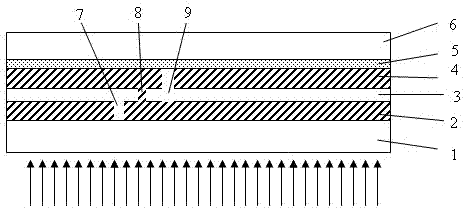
[0014] 1. Use ultra-clear float glass as the front transparent insulating substrate 1, and use low-pressure chemical vapor deposition technology or magnetron sputtering technology to deposit the front transparent conductive film 2 on the above-mentioned front transparent insulating substrate 1, as the front conductive electrode of the battery ;

[0015] 2. Use a 355nm or 1064nm laser to perform the first laser scribing 7 (Patten1) on the transparent conductive film 2 to realize the insulation between small areas, and use the above-mentioned laser to scribe P1 insulating lines around the edge of the component;

[0016] 3. Prepare an amorphous silicon semiconductor film layer 3 as a photoelectric conversion layer on the above-mentioned front tra...


PUM


Abstract

The invention relates to a method for manufacturing a solar thin film light transmitting component, belonging to the technical field of photovoltaic application. The manufacturing method adopts the following technical scheme: a front transparent electric conductive electrode, a thin film photoelectric conversion layer and a back electric conductive electrode are deposited on an insulating light transmitting substrate, and a plurality of son batteries are formed by cutting off the three thin films; then mechanical inscribing equipment is used for removing the front transparent electric conductive electrode, the thin film photoelectric conversion layer and the back electric conductive electrode (or the thin film photoelectric conversion layer and the back electric conductive electrode) in a direction parallel to or vertical to the son batteries, a pattern is inscribed by adjusting a needle head the equipment; as the photoelectric conversion layer in the patter is removed, therefore, lights can directly penetrate through the battery, thereby realizing the light transmitting function of the component. The manufacturing method can be used for realizing the preparation of the novel light transmitting component and has the characteristics of low cost, high efficiency, simple operation, short time consumption and the like while the output electrical property and the light transmission performance of the novel light transmitting component are not lower than that of the light transmitting component of the solar thin film battery prepared by the prior art.

Description

technical field [0001] The invention relates to a method for preparing a thin-film solar light-transmitting component, which belongs to the technical field of photovoltaic applications. Background technique [0002] At present, photovoltaic integrated buildings are the most advanced and potential high-tech green energy-saving buildings, and it is also one of the important directions for large-scale utilization of photovoltaic technology in the world. Building Integrated Photovoltaics (BIPV) refers to the installation of solar photovoltaic power generation arrays on the outer surface of the maintenance structure of the building to provide electricity. Since the combination of photovoltaic arrays and buildings does not occupy additional ground space, it is the best installation method for photovoltaic power generation systems to be widely used in cities, and thus has attracted much attention. According to the different combination forms of photovoltaic modules and buildings, ...

Claims


Application Information

Patent Timeline
Patent Type & Authority Applications(China)
IPC IPC(8): H01L31/18
CPCY02P70/50
Inventor 王辉王继存贾海军杜洁徐超麦耀华
Owner BAODING TIANWEI GRP CO LTD
Why Eureka
Try Eureka