
Method for realizing light transmission of thin film solar module by using vibrating mirror laser equipment

A technology of solar thin film and laser equipment, applied in laser welding equipment, electrical components, welding equipment and other directions, can solve problems such as affecting the efficiency and yield of components, unable to change graphics and patterns, affecting the electrical characteristics of batteries, etc., and achieve high work efficiency , flexible graphics changes, easy to achieve effects

Inactive Publication Date: 2011-11-09
BAODING TIANWEI GRP CO LTD +1
View PDF2 Cites 10 Cited by
  • Summary
  • Abstract
  • Description
  • Claims
  • Application Information

AI Technical Summary

Problems solved by technology

However, there are many insurmountable shortcomings in the above method: (1), firstly, the yield of this technology is low, and the area is 1.1×1.3m 2 1. Take a battery module with a light transmittance of 30% as an example. If the laser scribing speed reaches 1.5m / s, the diameter of the spot is usually 200μm. 30 minutes, not conducive to large-scale industrial production
(2) Secondly, this technology will introduce scratch defects, which will affect the electrical characteristics of the battery
Especially for products with high light transmittance requirements, the more linear grooves are scored, the more positions that intersect with the battery, and the greater the probability of scratching defects, which will reduce the performance of the component and seriously affect the reliability of the component. efficiency and productivity
(3) This method is limited to the linear grooves or light holes of parallel sub-cells or vertical sub-cells. In addition, the graphics and patterns cannot be changed, and the products produced are single and simple.

Method used


Image

  • Method for realizing light transmission of thin film solar module by using vibrating mirror laser equipment
  • Method for realizing light transmission of thin film solar module by using vibrating mirror laser equipment
  • Method for realizing light transmission of thin film solar module by using vibrating mirror laser equipment

Examples


Embodiment 1

[0028] The method for realizing the light transmission of the solar thin film battery module by applying the galvanometer laser device includes the following steps:

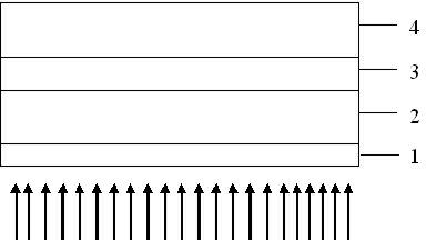
[0029] a. See attached figure 1 : On the float glass substrate 1, use low-pressure chemical vapor deposition technology or magnetron sputtering technology to deposit a transparent conductive film as the front electrode layer 2 of the battery; then use plasma chemical vapor deposition technology (PECVD) to coat the glass substrate Thin-film silicon p-i-n or p-i-n / p-i-n laminate structure and triple-junction silicon-based thin-film photoelectric conversion layer 3 are deposited on it; a transparent conductive film is grown on the above photoelectric conversion layer by low-pressure chemical vapor deposition technology as the back electrode layer 4 of the battery;

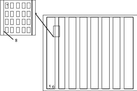
[0030] b. See attached figure 2 : the present embodiment adopts strip-shaped insulating area 5, and this area is used for carrying out light-transmitt...

Embodiment 2

[0038] The method for realizing the light transmission of the solar thin film battery module by applying the galvanometer laser device includes the following steps:

[0039] a. See attached figure 1 : On the float glass substrate 1, use low-pressure chemical vapor deposition technology or magnetron sputtering technology to deposit a transparent conductive film as the front electrode layer 2 of the battery; then use plasma chemical vapor deposition technology (PECVD) to coat the glass substrate Thin-film silicon p-i-n or p-i-n / p-i-n laminate structure and triple-junction silicon-based thin-film photoelectric conversion layer 3 are deposited on it; a transparent conductive film is grown on the above photoelectric conversion layer by low-pressure chemical vapor deposition technology as the back electrode layer 4 of the battery;

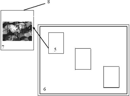
[0040] b. See attached image 3 : The present embodiment adopts a rectangular insulating area 5, which is used for light-transmitting treatment, and th...


PUM

PropertyMeasurementUnit
wavelengthaaaaaaaaaa
transmittivityaaaaaaaaaa

Abstract

The invention relates to a method for realizing the light transmission of a thin film solar module by using vibrating mirror laser equipment and belongs to the technical field of thin film solar batteries. The technical scheme is that: the method comprises the following steps of: depositing a front transparent conductive electrode, a thin film photoelectric conversion layer and a back conductive electrode on an insulation light transmission substrate; cutting off the three layers of thin films by adopting laser devices having different wavelengths so as to form insulation regions having different sizes and length-to-width ratios; and removing the three layers of thin films from the insulation regions by using laser scribing equipment with a vibrating mirror system, and scribing a pattern by changing an angle of a vibrating mirror and the magnitude of laser energy and switching laser on / off in real time, wherein film layers outside the insulation regions can realize a power generation function; at positions, where front glass is exposed out of, inside the insulation regions, light rays can be transmitted through the battery directly, so that a light transmission function of the module is realized. By the method, the preparation of a novel light transmission solar module is realized; the output electric performance and the light transmission performance of the thin film solar module are higher than those of the thin film solar module prepared in the prior art; and the method has the characteristics of low cost, high working efficiency, simple operation, diversified light transmission images, simple implementation and the like.

Description

technical field [0001] The invention relates to a light-transmitting method for a solar thin-film battery assembly using a vibrating mirror laser device, and belongs to the technical field of thin-film solar batteries. Background technique [0002] At present, building integrated photovoltaic (BIPV) building is the most advanced and most potential high-tech green energy-saving building, and it is also an important direction for large-scale use of photovoltaic technology in the world. BIPV refers to the installation of solar photovoltaic power generation phalanx on the outer surface of the maintenance structure of the building to provide electricity. Since the combination of photovoltaic arrays and buildings does not occupy additional ground space, it is the best installation method for photovoltaic power generation systems to be widely used in cities, and thus has attracted much attention. According to the different combination forms of photovoltaic modules and buildings, B...

Claims


Application Information

Patent Timeline
Patent Type & Authority Applications(China)
IPC IPC(8): H01L31/18B23K26/36B23K26/362
CPCY02P70/50
Inventor 杜洁王继存孙瑞萍佟鑫麦耀华贾海军
Owner BAODING TIANWEI GRP CO LTD
Learn More