Radio-frequency filter in mixed mode

A technology of radio frequency filters and duplexers, applied in waveguide devices, electrical components, circuits, etc., can solve the problems of small power capacity, high manufacturing cost, and large volume

Inactive Publication Date: 2012-03-14
ANHUI XRF TECH
View PDF2 Cites 5 Cited by
  • Summary
  • Abstract
  • Description
  • Claims
  • Application Information

AI Technical Summary

Problems solved by technology

At present, there are two most common filters on the market. One is a cavity filter composed of a metal coaxial resonant cavity. This filter is composed of a metal cavity and a metal resonant rod placed inside. It is characterized by inserting Small loss, high out-of-band suppression, and large power capacity, but its volume is large and the manufacturing co...

Method used


Image

  • Radio-frequency filter in mixed mode
  • Radio-frequency filter in mixed mode

Examples


Embodiment Construction

[0007] In order to make the technical problems, technical solutions and beneficial effects to be solved by the present invention clearer, the following further describes the present invention in detail with reference to the accompanying drawings and embodiments. It should be understood that the specific embodiments described here are only used to explain the present invention. It is not used to limit the present invention.

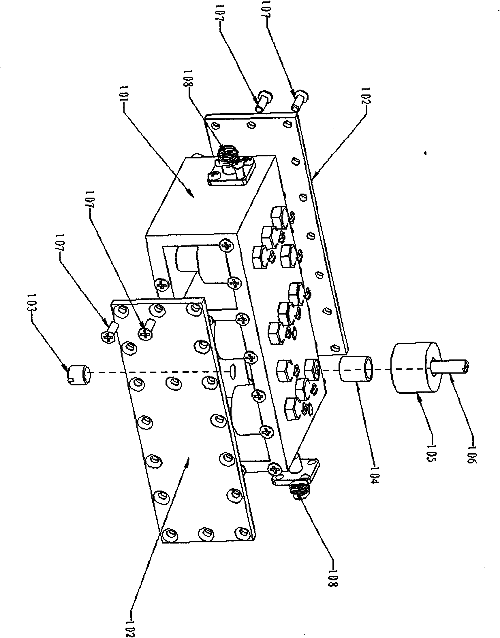
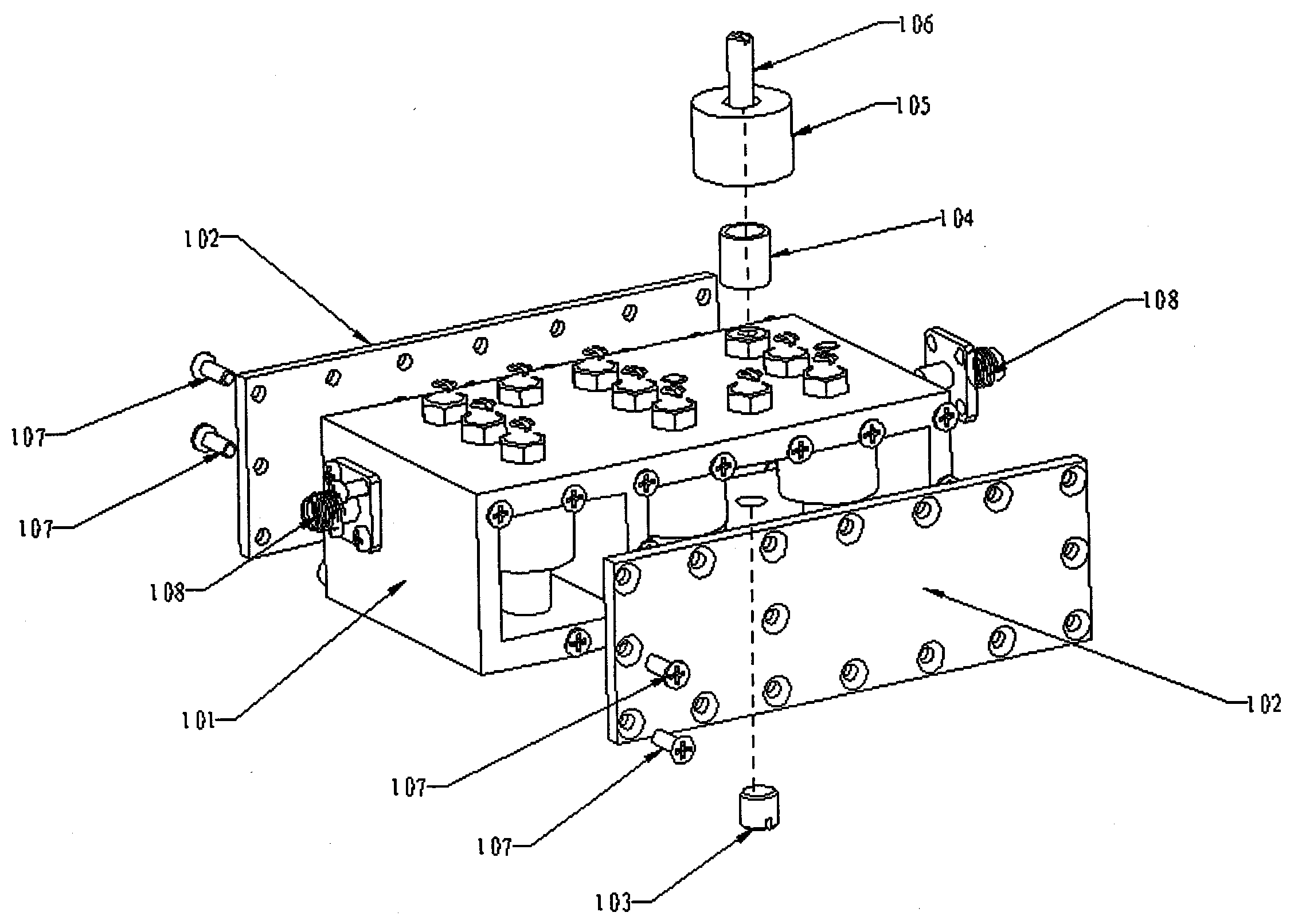
[0008] See figure 1 For this invention, the embodiment of the radio frequency filter provided by the present invention includes:

[0009] Metal cavity 101, side covers 102, bottom fastening bolts 103, metal resonance rod 104, dielectric resonator 105, top tuning rod 106, side cover fastening screws 107, input and output connectors 108,

[0010] The dielectric resonator 105 is connected to the top of the metal cavity 101, the top of the metal resonator rod 104 is connected to the other end of the dielectric resonator 105, and the bottom fastening bolt 103 passes ...


PUM


Abstract

The invention is suitable for the field of a filter and provides a radio-frequency filter and a duplexer. Two resonance modes are mixed in the radio-frequency filter, thereby greatly reducing the size of the filter, lowering the manufacturing cost of the filter and still acquiring higher electrical property and ultrahigh power capacity.

Description

Technical field [0001] The invention relates to a radio frequency filter. Background technique [0002] The radio frequency filter mainly plays a filtering role in wireless communication to extract the required signal. At present, there are two most common filters on the market. One is a cavity filter composed of a metal coaxial resonant cavity. This filter is composed of a metal cavity and a metal resonant rod placed inside. The loss is small, the out-of-band suppression is high, and the power capacity is large, but its volume is large and the manufacturing cost is relatively high. The other is a dielectric filter formed by etching a certain metal pattern on a ceramic medium. The biggest feature of this filter is its small size and low cost. However, the electrical performance of this filter is generally poor, and The power capacity is small, and the maximum power capacity currently on the market is 20W. Therefore, it is of great significance to develop a radio frequency filt...

Claims


Application Information

Patent Timeline
IPC IPC(8): H01P1/20H01P1/208
Inventor 方超王玉
Owner ANHUI XRF TECH
Why Eureka
Try Eureka