
Piezoelectric vibration piece, piezoelectric vibrator, oscillator, electronic device and radio-controlled timepiece

A technology of piezoelectric vibrating piece and vibrating wrist, which is applied in the field of radio clocks, can solve the problems of deviation of effective value with etching time, limitation of improvement of driving level characteristics, etc., and achieve good performance

Inactive Publication Date: 2012-03-14
SII CRYSTAL TECH
View PDF7 Cites 2 Cited by
  • Summary
  • Abstract
  • Description
  • Claims
  • Application Information

AI Technical Summary

Problems solved by technology

[0015] In this way, when the step portion is provided to connect the mounting portion and the intermediate portion, since the effective value deviates with the etching time, there is a limit to the improvement of the drive level characteristic.

Method used


Image

  • Piezoelectric vibration piece, piezoelectric vibrator, oscillator, electronic device and radio-controlled timepiece
  • Piezoelectric vibration piece, piezoelectric vibrator, oscillator, electronic device and radio-controlled timepiece
  • Piezoelectric vibration piece, piezoelectric vibrator, oscillator, electronic device and radio-controlled timepiece

Examples


Embodiment Construction

[0045] Embodiments of the present invention will be described below with reference to the drawings.

[0046] (Piezoelectric vibrating piece)

[0047] First, the piezoelectric vibrating piece will be described with reference to the drawings.

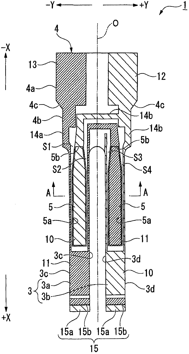
[0048] figure 1 is a plan view of the piezoelectric vibrating piece.

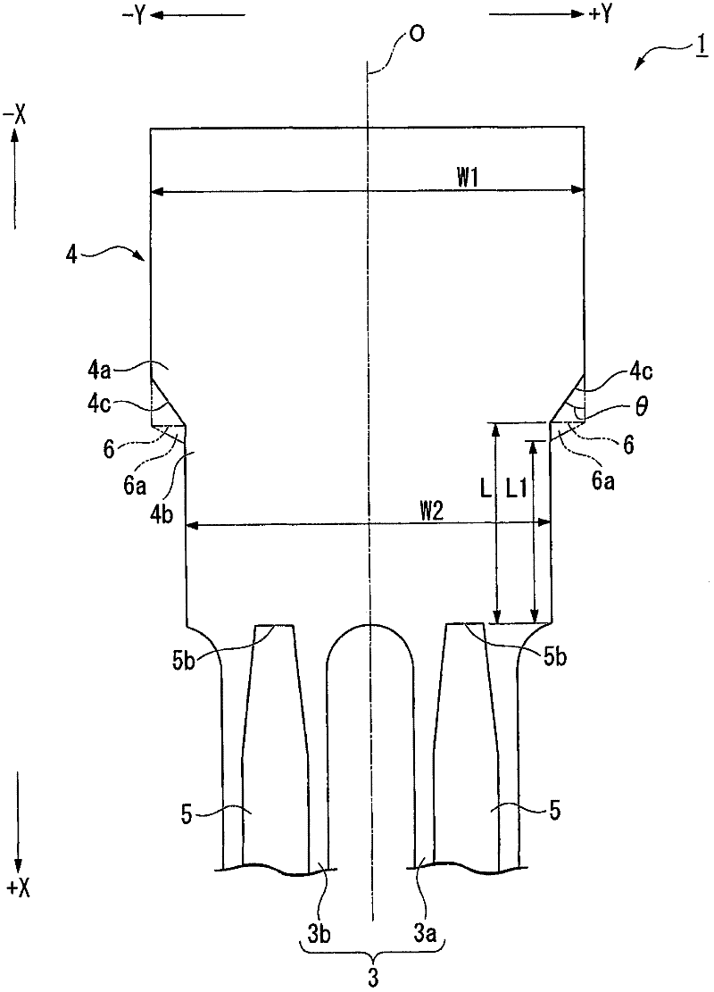
[0049] figure 2 is an enlarged view of the base of the piezoelectric vibrating piece.

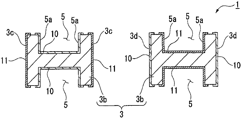
[0050] image 3 yes figure 1 A cross-sectional view of line A-A.

[0051] In addition, in the following description, the longitudinal direction of the piezoelectric vibrating reed is the X direction, the front end side is the +X side, and the base end side is the −X side. In addition, let the width direction of the piezoelectric vibrating reed be the Y direction, one side be the +Y side, and the other side be the −Y side.

[0052] Such as figure 1 As shown, the piezoelectric vibrating reed 1 is a tuning-fork vibrating reed made of piezoelectric materials such as crystal...


PUM


Abstract

A piezoelectric vibration piece that can ensure good drive level characteristics and a piezoelectric vibrator, oscillator, electronic device and radio-controlled timepiece in which the piezoelectric vibration piece is used are provided. The width of the base-end side of the grooves (5) is narrower than that of the tip side of the grooves (5). The base (4) includes: a mount section (4a) on the outer surface of which mount electrodes (12,13) are formed to mount the piezoelectric vibration piece (1); and an intermediate section (4b) that is connected to the mount section (4a) and the pair of vibrating arms (3a,3b) so as to be positioned between the mount section (4a) and the pair of vibrating arms (3a,3b), on the outer surface of which leading electrodes (14a,14b) that connect the pair of excitation electrodes (10,11) and the mount electrodes (12,13) are formed. The width of the mount section (4a) is wider than that of the intermediate section (4b). In step parts between the mount section (4a) and the intermediate section (4b), side surfaces of the mount section (4a) and side surfaces of the intermediate section (4b) are connected via tilted surfaces (4c) that tilt with respect to a longitudinal direction.

Description

technical field [0001] The invention relates to a piezoelectric vibrating piece, a piezoelectric vibrator, an oscillator, electronic equipment and a radio clock. Background technique [0002] In recent years, piezoelectric vibrators using crystals or the like as a time source, a timing source of a control signal, a reference signal source, etc. have been used in mobile phones and portable information terminal devices. Various types of such piezoelectric vibrators are known, but as one of them, a piezoelectric vibrator having a so-called tuning-fork type piezoelectric vibrating piece is known. [0003] However, further miniaturization of piezoelectric vibrating reeds is expected along with miniaturization of devices mounted therein. In general, as a method of suppressing the CI value (Crystal Impedance: Crystal Impedance) of the piezoelectric vibrator to be low and realizing the miniaturization of the piezoelectric vibrating piece, it is known to form ditch method. Further...

Claims


Application Information

Patent Timeline
Patent Type & Authority Applications(China)
IPC IPC(8): H03H9/21H03H3/02G04C9/02H01L41/09H01L41/18H03B5/32H03H9/02H03H9/19H03H9/215
CPCH03H9/21G04R20/10
Inventor 小林高志
Owner SII CRYSTAL TECH
Features
  • Generate Ideas
  • Intellectual Property
  • Life Sciences
  • Materials
  • Tech Scout
  • Unparalleled Data Quality
  • Higher Quality Content
  • 60% Fewer Hallucinations
Learn More