Supercharge Your Innovation With Domain-Expert AI Agents!

An open circuit protection circuit for a constant current drive circuit of a light emitting diode

A light-emitting diode, constant current drive technology, applied in emergency protection circuit devices, emergency protection circuit devices, circuit devices, etc. used to limit overcurrent/overvoltage, can solve problems such as output capacitor short circuit, circuit damage, and increased costs , to achieve the effect of reducing the volume

Active Publication Date: 2014-10-29
INVENTRONICS HANGZHOU
View PDF6 Cites 0 Cited by
  • Summary
  • Abstract
  • Description
  • Claims
  • Application Information

AI Technical Summary

Problems solved by technology

This circuit has the following disadvantages: when a load connected to the current sharing transformer T10 is open circuited, in order to make the other load connected to the current sharing transformer T10 work normally, it will cause overvoltage in the load branch corresponding to the open load, causing the circuit damage
[0005] However, the open-circuit protection circuit described in the prior art has the following disadvantages: figure 2 As shown, when the thyristor SCR10 is turned on, the output capacitor Co10 or Co20 is directly short-circuited
Due to the discharge of the output capacitor Co10 or Co20, the devices including SCR10 are subjected to a large current stress, so it is necessary to use a device that can withstand a large current, which increases the cost

Method used


Image

  • An open circuit protection circuit for a constant current drive circuit of a light emitting diode
  • An open circuit protection circuit for a constant current drive circuit of a light emitting diode
  • An open circuit protection circuit for a constant current drive circuit of a light emitting diode

Examples


Embodiment 3

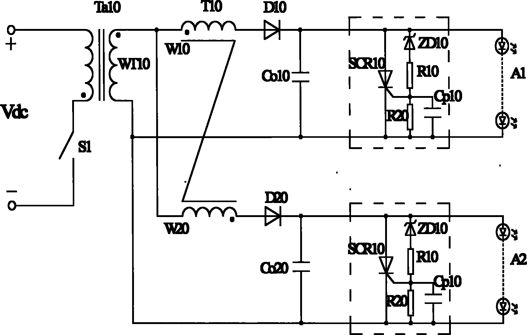
[0100] In the third embodiment, the detection control unit 202 is used to detect the output voltage of the second rectification sub-circuit, and output a control signal when the output voltage of the second rectification sub-circuit is not lower than the preset second threshold to the processing unit 201.

[0101] The processing unit 201 is configured to short-circuit the first end a2 and the second end b2 of the processing unit 201 when receiving the control signal, and then short-circuit the output end of the second rectifier sub-circuit connected in series with the first current equalizing winding W1 .

[0102] In the third embodiment, taking the first load branch as an example, when the load A1 is open, when the detection control unit 202 detects that the output voltage of the second rectifier sub-circuit is not lower than the preset second threshold , outputting a control signal to the processing unit 201, and short-circuiting the first terminal a2 and the second termina...


PUM


Abstract

The invention provides an open-circuit protection circuit of a light-emitting diode constant-current driving circuit, which is characterized in that the open-circuit protection circuit comprises a transformer, the transformer is provided with at least one secondary winding and the secondary winding is connected with at least two loops of load braches to divide each load branch into two load subbranches and further form two rectification subloops; the current equalizing winding of a current equalizing transformer is serially connected with one rectification subloop of each load branch; and each load branch is respectively connected with an open-circuit protection module which comprises a detection control unit and a processing unit, wherein the detection control unit is used for outputting a control signal to the processing unit when the output voltage of each load branch or voltage in proportion to the output voltage is detected to be not lower than the corresponding preset threshold, and the processing unit is used for short-circuiting the output end of the rectification subloop in which the load subbranch exists and which is serially connected with the current equalizing winding after the control signal is received. By adopting the open-circuit protection circuit provided by the embodiment of the invention, the cost can be decreased and the volume of the current equalizing transformer can be reduced.

Description

technical field [0001] The invention relates to a constant current drive circuit, in particular to an open circuit protection circuit for a light emitting diode constant current drive circuit. Background technique [0002] In a multi-output light emitting diode (LED, Light Emitting Diode) constant current drive circuit, each load is composed of one or more LED lamps. When the two load voltages are different, it is necessary to balance the two load currents, that is, to realize that the total current output by the constant current drive circuit is distributed to each LED load according to the load requirements. [0003] refer to figure 1 , is a typical LED constant current drive circuit diagram. The transformer Ta10 includes a secondary winding WT10, connected to two rectification circuits, and supplies power to two loads A1 and A2. This circuit realizes the balance on the two load branches A1 and A2 through a current equalizing transformer T10. If the load is more than t...

Claims


Application Information

Patent Timeline
Patent Type & Authority Patents(China)
IPC IPC(8): H05B37/02H02H9/04H02H9/02
Inventor 葛良安姚晓莉
Owner INVENTRONICS HANGZHOU
Features
  • R&D
  • Intellectual Property
  • Life Sciences
  • Materials
  • Tech Scout
  • Unparalleled Data Quality
  • Higher Quality Content
  • 60% Fewer Hallucinations
Learn More