
Blast furnace superconducting cooling and waste heat power generation system

A waste heat power generation and power generation system technology, applied in blast furnaces, cooling devices, blast furnace details, etc., can solve the problems of large influence area of ​​cooling unit, poor cooling stability, short life of furnace lining, etc., to reduce manual adjustment errors, reduce Heat loss, the effect of a high degree of automation

Inactive Publication Date: 2013-02-13
CHENGDU SINOMETALLURGY ENERGY CONSERVATION ENVIRONMENTAL PROTECTION ENG CO LTD
View PDF4 Cites 0 Cited by
  • Summary
  • Abstract
  • Description
  • Claims
  • Application Information

AI Technical Summary

Problems solved by technology

[0010] Therefore, the current blast furnace cooling technology cannot meet the normal temperature field requirements of the blast furnace. Its cooling stability is poor, adjustment is difficult, and it is prone to problems such as tube explosion, red furnace shell, short life of the furnace lining, and large affected area after the cooling unit is damaged.

Method used


Image

  • Blast furnace superconducting cooling and waste heat power generation system
  • Blast furnace superconducting cooling and waste heat power generation system
  • Blast furnace superconducting cooling and waste heat power generation system

Examples


Embodiment

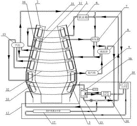
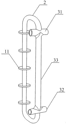
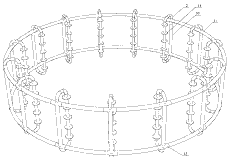
[0040] Such as Figure 1~3 As shown, the blast furnace body 1 of the present invention is the same as the traditional blast furnace, and is divided into four parts, the furnace shaft, the bosh, the furnace waist and the furnace seat. The present invention is provided with more than one superconducting annular heat exchange ring 2 in a layered and surrounding manner along the side wall of the blast furnace body 1, that is, these superconducting annular heat exchange rings 2 are arranged along the shaft and bosh of the blast furnace body 1. , the furnace waist and the furnace seat are arranged, and the side wall surface of the entire blast furnace body 1 is completely covered. Every circle around the side wall of the blast furnace body 1 is a layer, and the midline points of all superconducting annular heat exchange rings 2 on the same layer are in the same plane, so along the side wall surface of the blast furnace body 1 A superconducting annular heat exchange ring 2 with seve...


PUM

PropertyMeasurementUnit
particle diameteraaaaaaaaaa
diameteraaaaaaaaaa

Abstract

The invention discloses a blast furnace superconducting cooling and waste heat power generation system. The system is composed of a blast furnace body (1), a power generation system (12) and a steam utilization device. The system is characterized in that more than one superconducting ring type heat exchange ring (2) is arranged along the side wall of the blast furnace body (1) in a layering and surrounding mode; each superconducting ring type heat exchange ring (2) is provided with a pouring solidification body (10) formed by using wear-resisting thermal-shock-resisting carburizing-resisting elastic castable refractory; each superconducting ring type heat exchange ring (2) is embedded in the inner lining of the side wall of the blast furnace body (1) through the pouring solidification body (10); and the like. According to the invention, hot water subjected to heat exchange is intently led out through the superconducting ring type heat exchange ring and an annular pipeline system corresponding to the superconducting ring type heat exchange ring, thus heat exchange intensity is enlarged, and heat exchange efficiency and cooling efficiency are improved; and the traditional cooling water temperature is improved to 250 DEG C from 40 DEG C, and then the cooling water is overheated to 400 DEG C through applying the superconducting ring type heat exchange ring twice, so that cooling waste heat can be utilized for power generation.

Description

technical field [0001] The invention relates to a blast furnace cooling heat efficient power generation system, in particular to a blast furnace superconducting cooling and waste heat power generation system. Background technique [0002] During the blast furnace production process, the cooling of the furnace wall requires a large amount of water to take away the heat to reduce the temperature of the furnace wall, so as to meet the process temperature requirements of the normal production of the blast furnace. The waste heat taken away by the cooling of the blast furnace and the heat dissipation from the surface of the blast furnace wall account for 5% and 0.5% of the total heat consumption of the blast furnace respectively. Based on the simple calculation that 400-800Kg of coke is needed to produce one ton of pig iron, there are about 20-40Kg of coke produced Thermal energy is dissipated in the form of cooling water heat. Based on the 600 million tons of iron produced annu...

Claims


Application Information

Patent Timeline
Patent Type & Authority Patents(China)
IPC IPC(8): C21B7/10C21B7/00
Inventor 王蓉
Owner CHENGDU SINOMETALLURGY ENERGY CONSERVATION ENVIRONMENTAL PROTECTION ENG CO LTD
Learn More