Check patentability & draft patents in minutes with Patsnap Eureka AI!

Engine and cooling system for engine

A cooling system and engine technology, applied to the cooling of the engine, engine components, machines/engines, etc., can solve the problem of low cooling efficiency, achieve the effect of improving cooling efficiency, reducing flow rate, and enhancing cooling effect

Active Publication Date: 2013-04-24
CHINA HANGFA SOUTH IND CO LTD
View PDF6 Cites 0 Cited by
  • Summary
  • Abstract
  • Description
  • Claims
  • Application Information

AI Technical Summary

Problems solved by technology

[0004] The purpose of the present invention is to provide a cooling system for an engine to solve the technical problems of low cooling efficiency and large temperature difference between hot and cold arc regions of the engine in the prior art

Method used


Image

  • Engine and cooling system for engine
  • Engine and cooling system for engine
  • Engine and cooling system for engine

Examples


Embodiment Construction

[0023] The embodiments of the present invention will be described in detail below with reference to the accompanying drawings, but the present invention can be implemented in many different ways defined and covered by the claims.

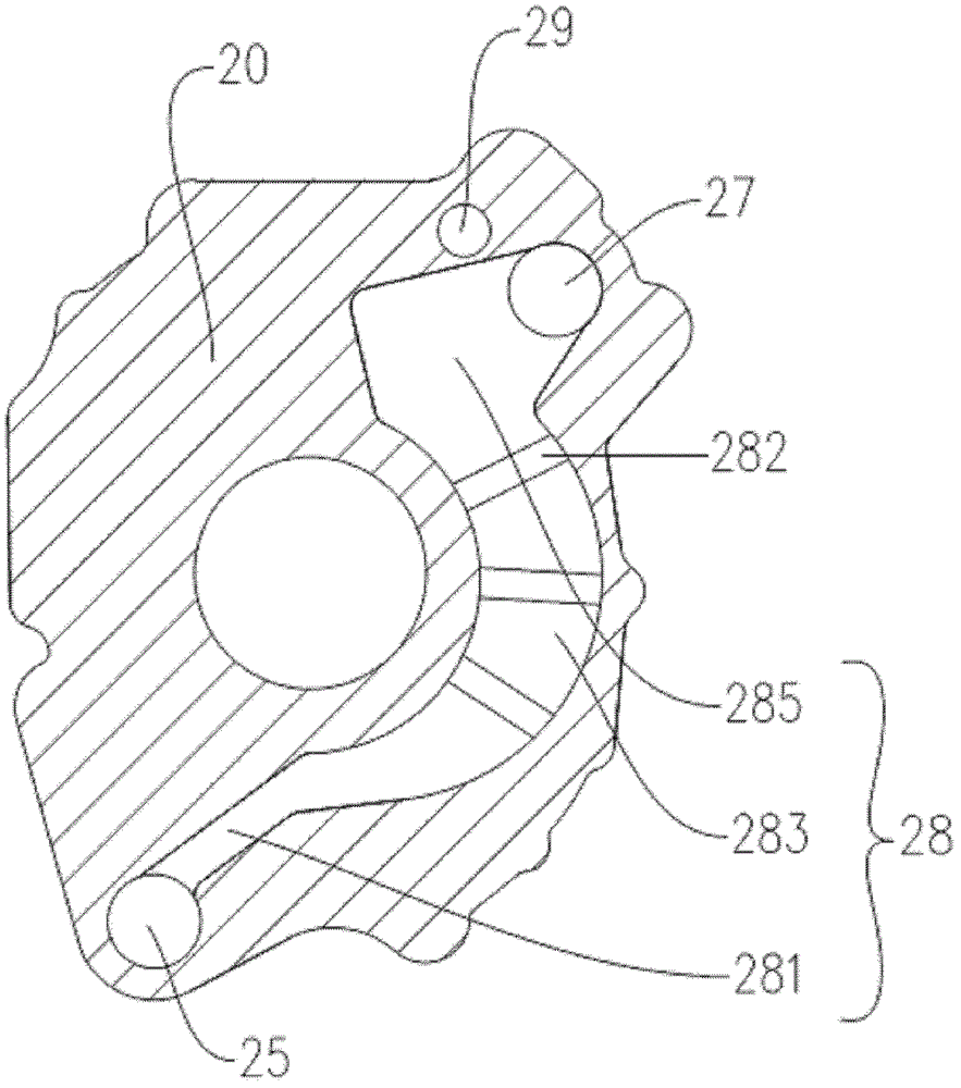
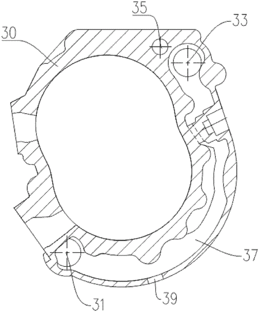
[0024] Please refer to figure 1 The cooling system of the engine of the preferred embodiment of the present invention includes a coolant pump 10 , a front cylinder head 20 , a cylinder block 30 , a rear cylinder head 40 , a temperature control valve 50 and a radiator 60 installed on the rear cylinder head 40 . The cooling pump 10 is fixed to the front cylinder head 20 . The front cylinder head 20 and the rear cylinder head 40 are respectively fixed on two opposite sides of the cylinder block 40 . The radiator 60 is respectively connected between the temperature control valve 50 and the coolant pump 10 to discharge the heated coolant from the engine into the coolant pump 10 so as to supply the cooling system of the present invention for circulation....


PUM


Abstract

The invention provides a cooling system for an engine. The cooling system comprises a front cylinder cover, a cylinder body and a rear cylinder cover, wherein the front cylinder cover and the rear cylinder cover are arranged on two side faces of the cylinder body; the front cylinder cover is provided with a bent channel, an outlet and an inlet; two ends of the channel are connected with the inletand the outlet; the width of the position of the channel connected with the outlet is greater than that of the position of the channel connected with the inlet; the cylinder body is provided with a first flowing port, a second flowing port and a bent through groove; the rear cylinder cover is provided with a blind hole, a collecting tank and a bent flow channel; the width of the position of the flow channel connected with the blind hole is greater than that of the position of the flow channel connected with the collecting tank; and cooling fluid in the engine passes through the collecting tank and flows back to a cooling fluid supply source to fully cool the front cylinder cover, the cylinder body and the rear cylinder cover, and the cooling efficiency is improved. Moreover, by the bent arc design and dimension change design of the channel, the through groove and the flow channel, the flow rate of the cooling fluid is reduced, the retention time of the cooling fluid in the front cylinder cover, the cylinder body and the rear cylinder cover is prolonged, and the cooling effect is enhanced.

Description

technical field [0001] The present invention relates to the field of cooling systems, in particular, to an engine cooling system. Furthermore, the invention also relates to an engine having the above-mentioned cooling system. Background technique [0002] When the rotary engine is working, the heating conditions of various parts of the body are different. The temperature in the intake and compression sections is relatively low, which becomes the cold arc zone; while the temperature in the combustion expansion and exhaust section is relatively high, called the hot arc zone. The disparity in temperature between these two sections seriously affects the reliability and life of the engine. [0003] Now the water-cooled cooling method is commonly used to cool the hot arc area of ​​the engine. However, the existing cooling water circulation method and water channel structure are simple, unable to effectively cool the hot arc area of ​​the rotor engine body, and the cooling effici...

Claims


Application Information

Patent Timeline
Patent Type & Authority Patents(China)
IPC IPC(8): F02F1/14F02F1/38F01P7/16F01P5/10
Inventor 沈秀利贺俊谢振兰李桃袁雪松
Owner CHINA HANGFA SOUTH IND CO LTD
Features
  • R&D
  • Intellectual Property
  • Life Sciences
  • Materials
  • Tech Scout
  • Unparalleled Data Quality
  • Higher Quality Content
  • 60% Fewer Hallucinations
Learn More