Energy conversion system used in intensified geothermal system with CO2 as working medium

An energy conversion system and working fluid technology, applied in geothermal energy systems, geothermal energy power generation, etc., can solve problems affecting geothermal fluid heat absorption, water loss, and low efficiency, so as to improve heat utilization rate, reduce emissions, and simplify the system Effect

Inactive Publication Date: 2012-03-21
TSINGHUA UNIV
View PDF3 Cites 17 Cited by
  • Summary
  • Abstract
  • Description
  • Claims
  • Application Information

AI Technical Summary

Problems solved by technology

However, the use of water as geothermal fluid has some disadvantages: 1. The water injected into the ground is seriously lost, with a loss rate as low as 10% and as high as 78%.
2. For heat sources with a temperature higher than the critical temperature of water, due to the dissolution and precipitation of minerals due to the thermochemical interaction between water and rock formations, short circuits or blockages occur between injection wells and production wells, which affect geothermal fluids endothermic
However, using CO 2 The conversion of thermal energy into electricity by using water as geothermal fluid and directly entering the energy conversion system is less efficient than the flash cycle using water as geothermal fluid, which becomes 2 Barriers to EGS deployment as geothermal fluids

Method used


Image

  • Energy conversion system used in intensified geothermal system with CO2 as working medium
  • Energy conversion system used in intensified geothermal system with CO2 as working medium
  • Energy conversion system used in intensified geothermal system with CO2 as working medium

Examples


Embodiment Construction

[0015] The present invention will be described in detail below with reference to the drawings and embodiments.

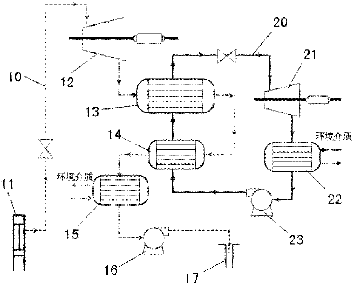
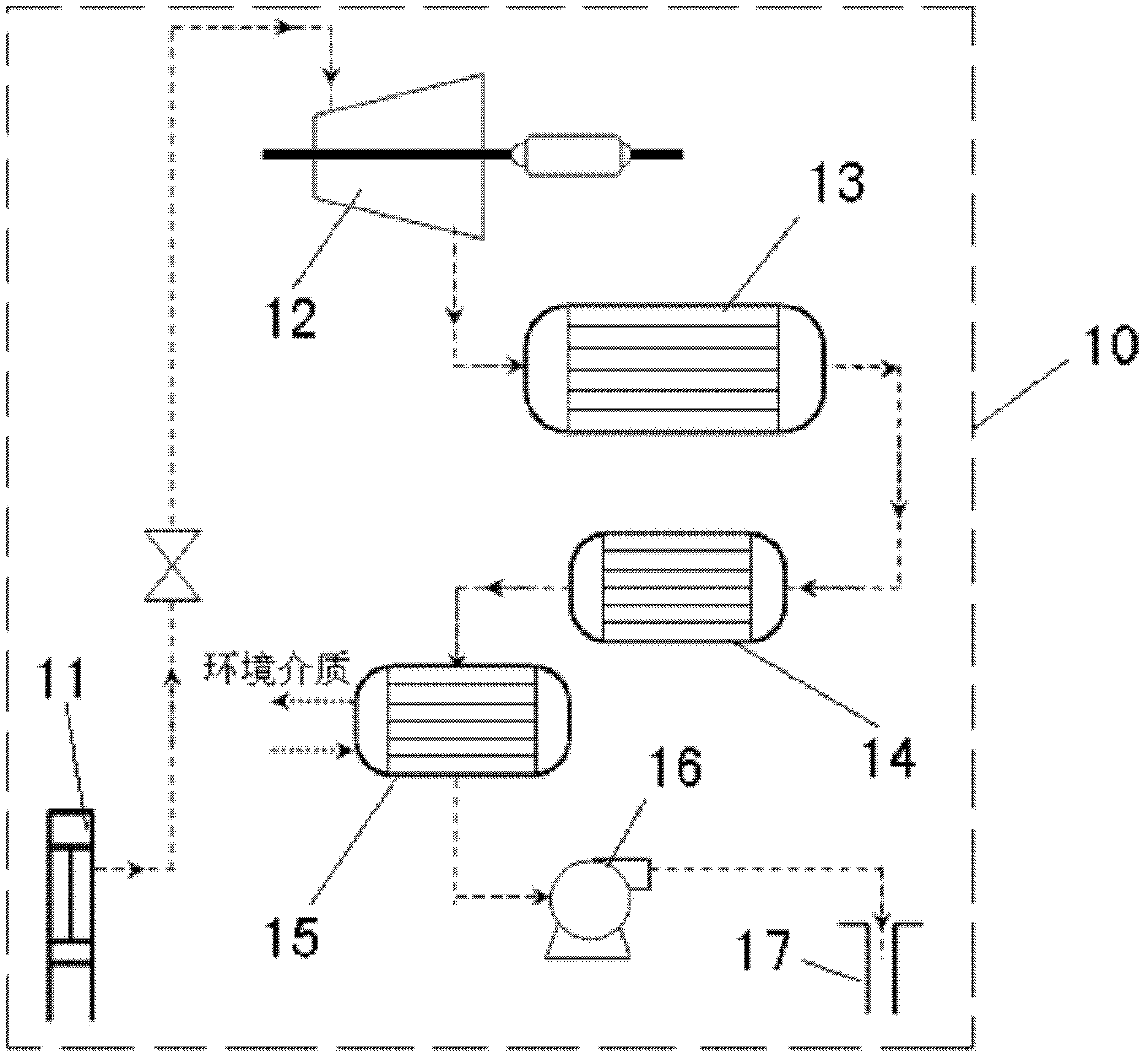
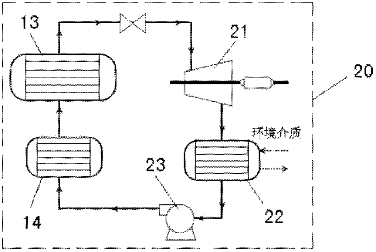
[0016] Such as figure 1 As shown, the present invention includes ultra-high pressure CO 2 Thermal power generation system 10 and organic Rankine thermal power generation system 20, ultra-high pressure CO 2 The thermal power generation system 10 uses CO that absorbs heat in the geothermal reservoir 2 As a working fluid, the thermal energy is converted into electric energy by turbine expansion and work; the Rankine cycle working fluid and CO after work in the organic Rankine thermal power generation system 20 2 Exhaust steam heat exchange, after Rankine cycle, the heat energy is converted into electric energy. Therefore, the conversion efficiency of the present invention can be improved, the heat utilization rate of the geothermal system can be improved, and part of the CO 2 Long-term storage, reducing CO 2 Emissions to the atmosphere.

[0017] Such as figure 1 , figure 2 ...


PUM


Abstract

The invention relates to an energy conversion system used in an intensified geothermal system with CO2 as a working medium. The energy conversion system is characterized by comprising a ultrahigh-voltage CO2 thermal power generation system and an organic rankine thermal power generation system, wherein endothermic CO2 in a geothermal reservoir is taken as the working medium for the ultrahigh-voltage CO2 thermal power generation system, and heat energy is converted into electric energy through turbine expansion working; and a rankine cycle working medium in the organic rankine thermal power generation system exchanges heat with CO2 subjected to working doing, and the heat energy is converted into the electric energy through a rankine cycle. According to the invention, because the ultrahigh-voltage CO2 thermal power generation system and the organic rankine thermal power generation system are combined in use, the conversion efficiency in converting the heat energy into the electric energy is effectively increased; meanwhile, the heat utilization rate of the geothermal system is increased, long-term sequestration of partial CO2 can be realized, and the emission of the CO2 to the atmosphere is reduced. The energy conversion system disclosed by the invention can be widely applied to the technical field of geothermal power generation.

Description

Technical field [0001] The invention relates to an energy conversion system in the technical field of geothermal power generation, in particular to an energy conversion system for CO 2 It is the energy conversion system in the enhanced geothermal system (EGS) of the working fluid. Background technique [0002] Geothermal resources are rock thermal energy, geothermal fluid heat and associated useful components that can be scientifically and reasonably developed from the crust under current technical and economic conditions and geological conditions. At present, the world's mining of geothermal energy for power generation is faster and faster, and the mining depth is getting deeper and deeper. Power generation systems used for power generation from medium and low temperature geothermal resources, such as dual working fluid cycle, flash vaporization, Kalina cycle and other system technologies, are gradually mature and have a certain commercial basis. [0003] EGS is the abbreviation ...

Claims


Application Information

Patent Timeline
Patent Type & Authority Applications(China)
IPC IPC(8): F03G4/00
CPCY02E10/10
Inventor 姜培学张富珍胥蕊娜
Owner TSINGHUA UNIV
Why Eureka
Try Eureka