
On-line loading test stand shift mechanism of manual transmission

A manual gearbox and loading test technology, which is applied in the direction of machine gear/transmission mechanism testing, etc., can solve the problems of low automation of manual gearbox test bench, undetectable force and displacement of gear shifting, difficulty in starting time and ending time Measurement and other issues, to achieve the effect of compact structure, no pollution of power source, and low noise

Active Publication Date: 2012-03-21
ANHUI JEE AUTOMATION EQUIP CO LTD
View PDF6 Cites 11 Cited by
  • Summary
  • Abstract
  • Description
  • Claims
  • Application Information

AI Technical Summary

Problems solved by technology

[0003] At present, the degree of automation of the manual transmission test bench is relatively low, and traditional production relies on the manual operation of workers. For the transmission fatigue life test, continuous shift operations of 200,000 to 400,000 times are required, and manual work is time-consuming and laborious; not only In this way, manual gear shifting cannot detect the strength and displacement of gear shifting, and it is also difficult to measure the starting and ending moments of gear shifting. This form seriously affects the accurate judgment of the performance of the gear shifting mechanism.
[0004] Most of the existing shifting manipulators use pneumatic or hydraulic methods, which can realize simple stroke shifting operations, but the structure of the actuator is complex and difficult to maintain; the positioning accuracy of the manipulator is not high, and the flexibility of the shifting mechanism is not high. Once the gearbox The stroke or gear changes, the actuator needs to be redesigned, and the versatility is poor; it is difficult to accurately judge the performance of the test piece due to the inability to complete the data collection

Method used


Image

  • On-line loading test stand shift mechanism of manual transmission
  • On-line loading test stand shift mechanism of manual transmission
  • On-line loading test stand shift mechanism of manual transmission

Examples


Embodiment Construction

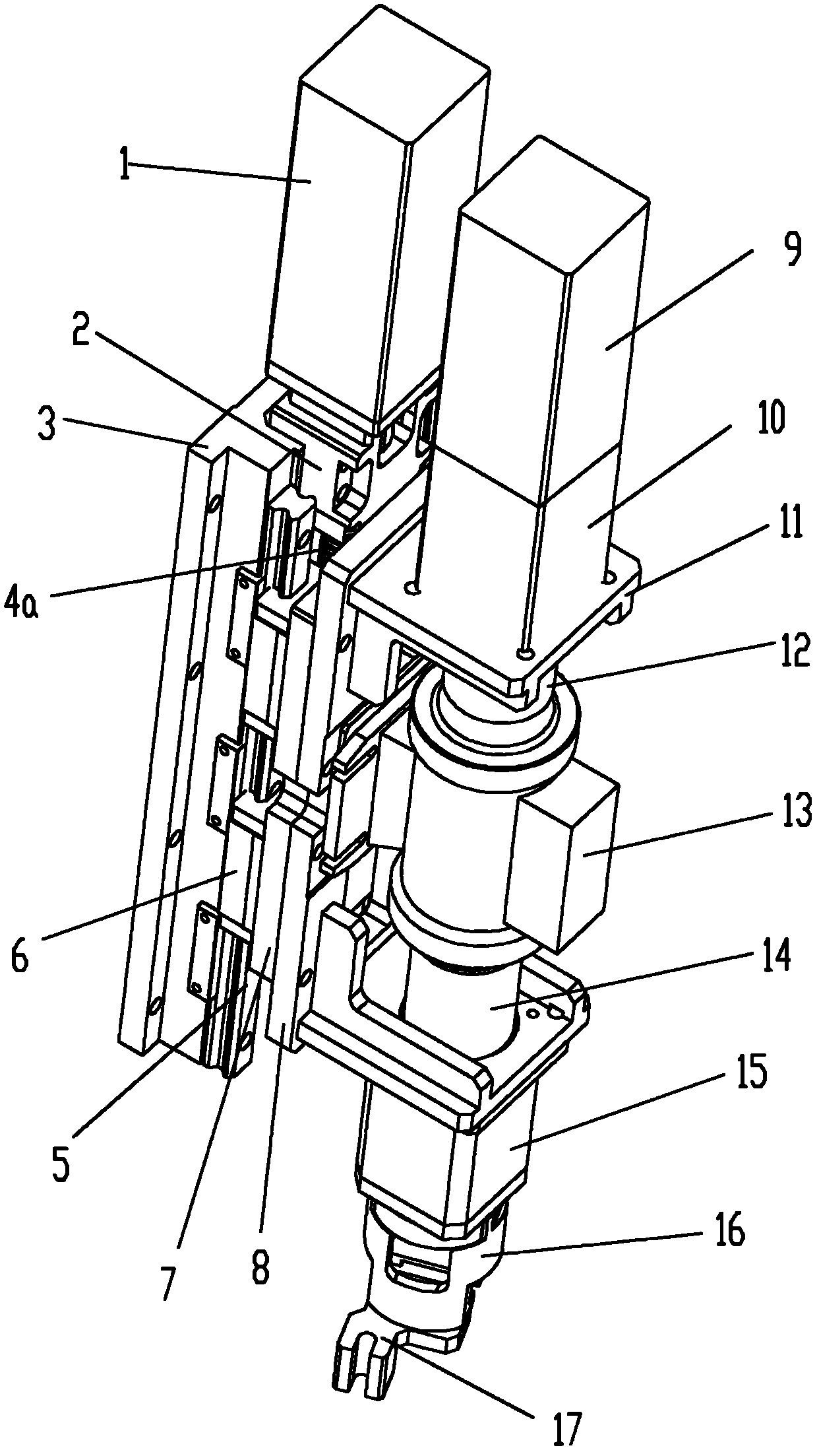
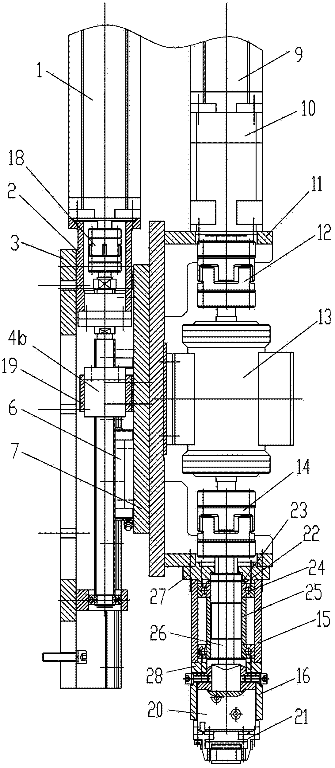
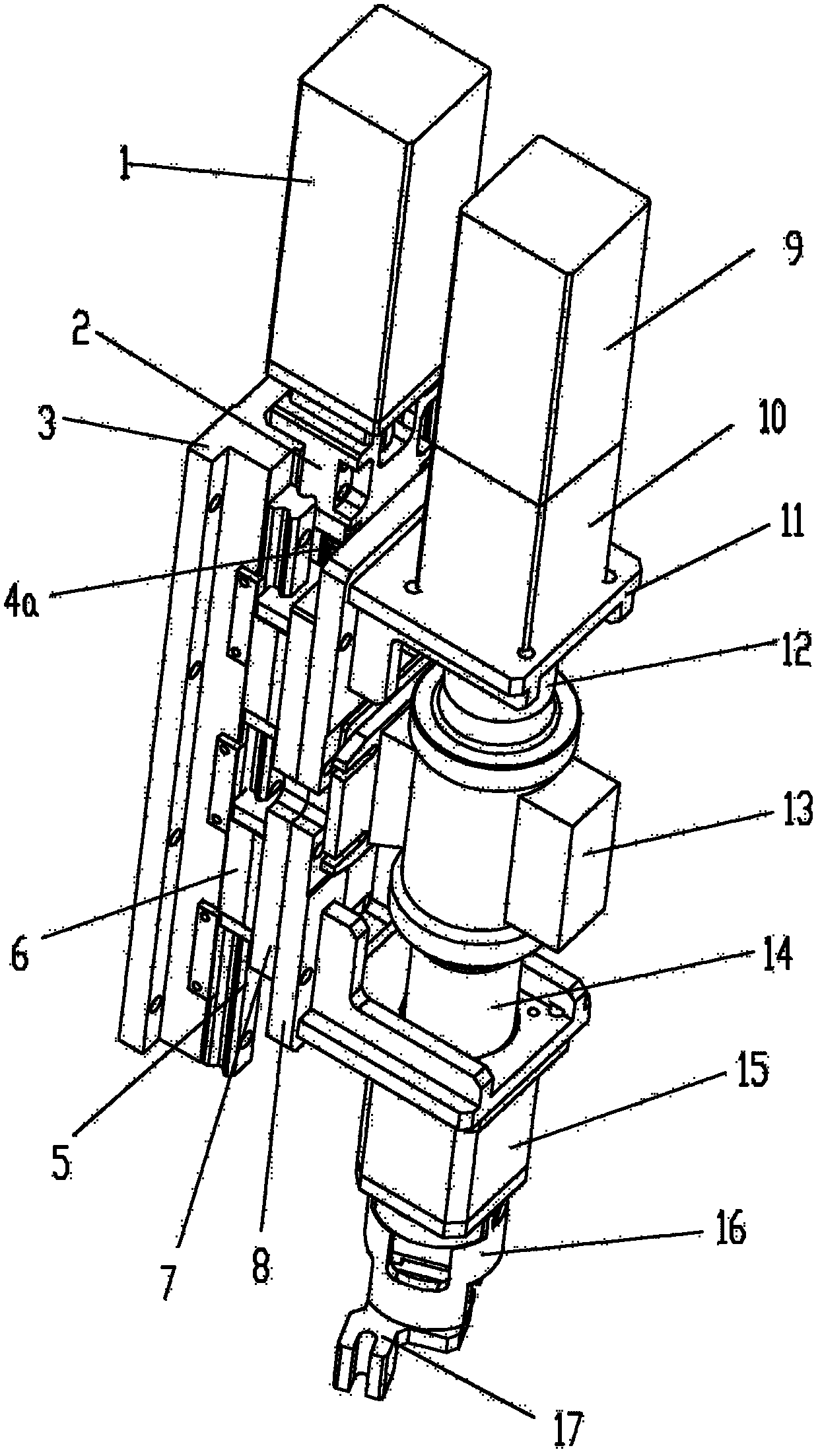
[0024] see figure 1 , figure 2 , the manual gearbox in this embodiment is provided with:

[0025] The gear selection unit is to fix the gear selection servo motor 1 on the base frame 3 through the motor mounting base 2, the gear selection servo motor 1 is axially connected with the ball screw 4a through the first coupling 18, and the screw slide 7 is connected through the nut The bracket 19 is fixedly connected with the lead screw nut 4b, and the lead screw nut 4b is threadedly matched with the ball screw 4a, and the gear selection servo motor 1 drives the lead screw slide 7 to slide along the axial direction of the ball screw 4a;

[0026] The gear shift unit is directly connected to the gear reducer 10 by the gear shift servo motor 9, the gear reducer 10 is coupled to the torque sensor 13 through the second coupling 12, and the torque sensor 13 is coupled to the drive shaft 26 through the third coupling 14. A gear shift head is arranged at the shaft end of the power transm...


PUM


Abstract

The invention discloses an on-line loading test stand shift mechanism of a manual transmission.The on-line loading test stand shift mechanism is characterized in that a gear selection unit is arranged and has a working principle that a gear selection servo motor drives a screw sliding table to slide along the axial direction of a ball screw; a gear shift unit has a working principle that a gear shift servo motor drives a gear shift shifting head through a transmission shaft to rotate for a set angle; the transmission shaft in the gear shift unit and the ball screw in the gear selection unit are in the same axial direction; the gear shift unit is supported by a gear shift unit support plate; the gear shift unit support plate is fixedly connected with the screw sliding table; and the screw sliding table drives the gear shift unit to slide along the axial direction of the ball screw. The on-line loading test stand shift mechanism has the advantages of simple structure and high control precision and can act accurately and reliably, and the manual transmission can automatically shift gears.

Description

technical field [0001] The invention relates to a test equipment, in particular to an automatic shift mechanism applied on a manual transmission line loading test stand. Background technique [0002] The gearbox is the core component of the vehicle transmission system, and its safety and reliability are directly related to the safety of the occupants' lives and property. Therefore, the gearbox needs to be tested on the test bench before leaving the factory to check its possible potential assembly manufacturing and design problems. defect. [0003] At present, the degree of automation of the manual transmission test bench is relatively low, and traditional production relies on the manual operation of workers. For the transmission fatigue life test, continuous shift operations of 200,000 to 400,000 times are required, and manual work is time-consuming and laborious; not only In this way, manual gear shifting cannot detect the strength and displacement of gear shifting, and it...

Claims


Application Information

Patent Timeline
Patent Type & Authority Applications(China)
IPC IPC(8): G01M13/02
Inventor 林巨广蔡高坡
Owner ANHUI JEE AUTOMATION EQUIP CO LTD
Learn More