Sampling type size density measuring method
A technology of density measurement and slurry, which is applied in the direction of measuring device, specific gravity measurement, and determination of specific gravity by measuring pressure difference, etc. It can solve problems such as inaccurate measurement, use of radioactive sources, easy blockage, etc., and achieve the effect of ensuring accuracy
- Summary
- Abstract
- Description
- Claims
- Application Information
AI Technical Summary
Problems solved by technology
Method used
Image
Examples
Embodiment 1
[0052] Option 1, pressure method one
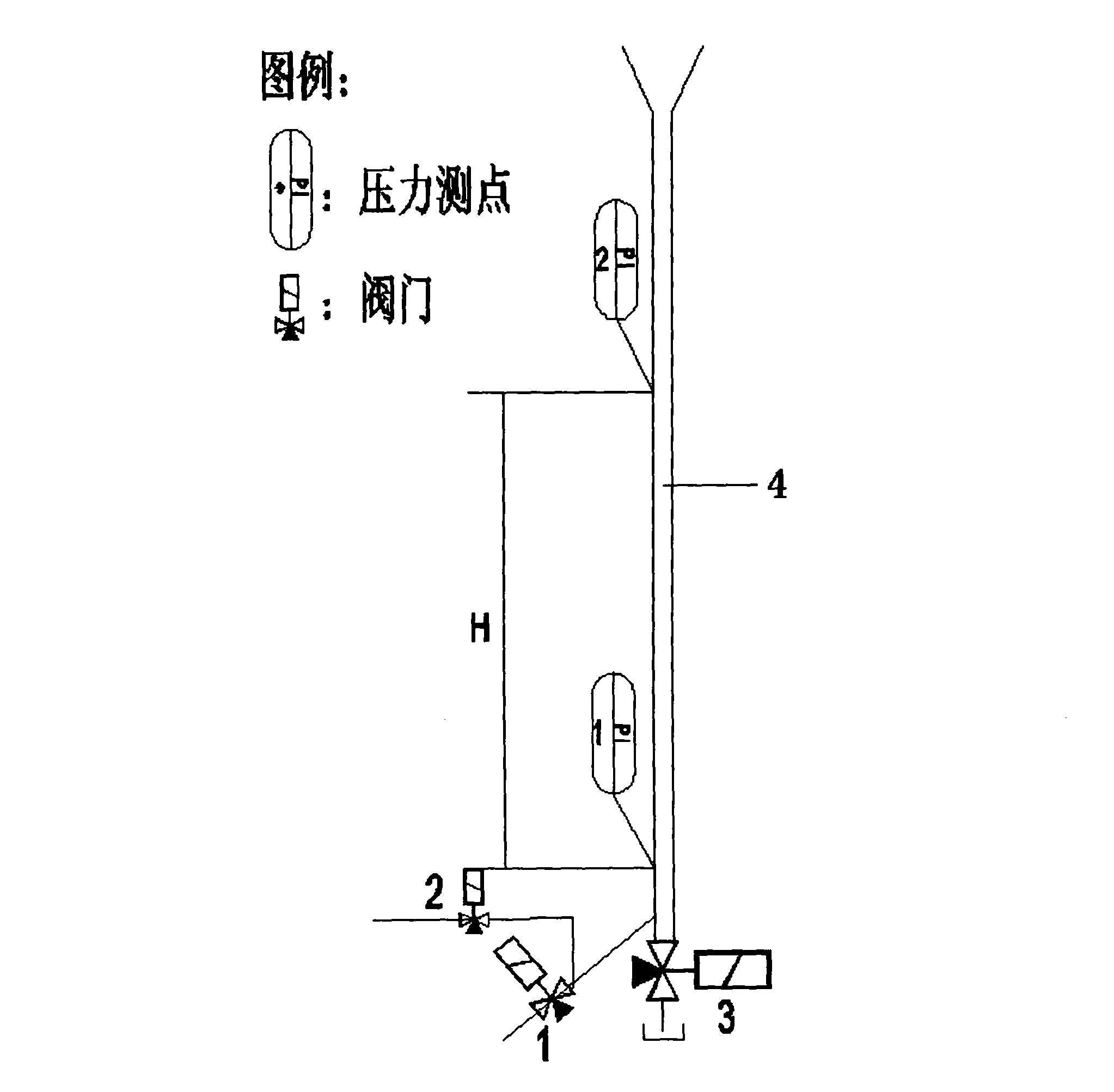
[0053] Such as figure 1 As shown in the connection diagram of the dual pressure transmitter equipment, the slurry sample pipe 4 is connected to the bottom of the slurry absorption tower or the outlet branch of the gypsum slurry discharge pump (omitted in the figure) through the first electromagnetic-pneumatic valve 1, and through the second electromagnetic-pneumatic valve 2 Connect the industrial water pipeline, and connect the drain pipeline through the third electromagnetic-pneumatic valve 3.
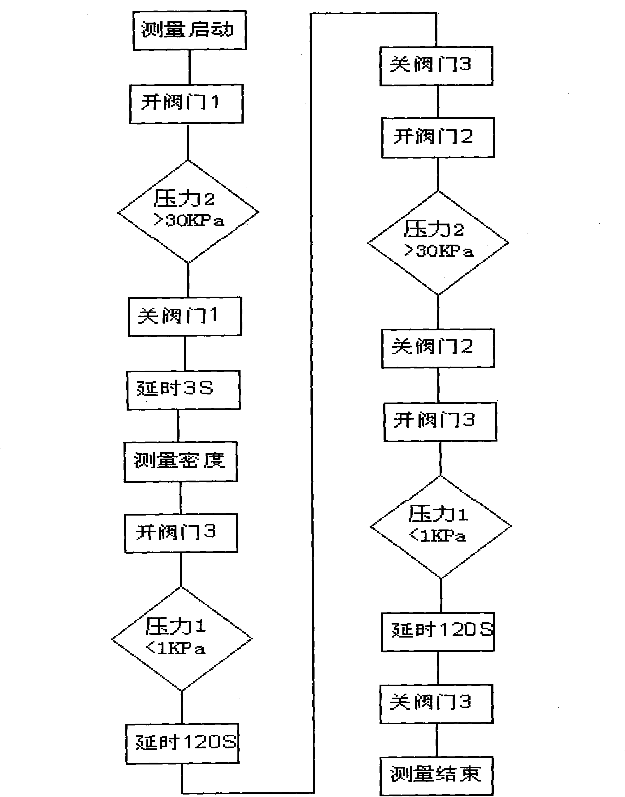
[0054]Two pressure measuring points are set on the slurry sample tube, the height difference between the two pressure measuring points is H, and the two pressure measuring points are connected to a pressure transmitter (not shown in the figure). At the beginning of the measurement, open valve 1 at regular intervals (such as half an hour), judge the amount of slurry entering the slurry sample tube according to the signal of pressure measuring poi...
Embodiment 2
[0058] Option 2, pressure method 2
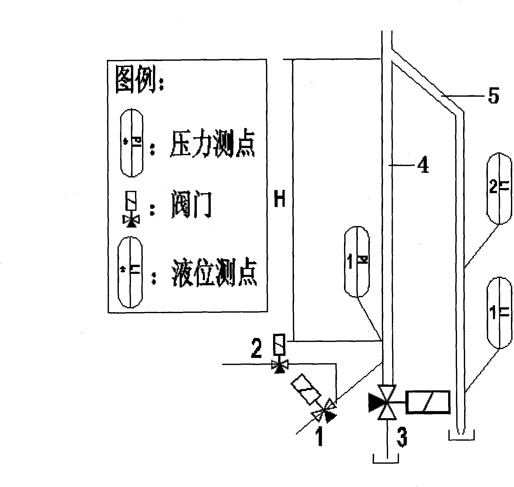
[0059] Such as image 3 The equipment connection diagram of the single pressure transmitter scheme shown in the figure, only one pressure measuring point is set on the slurry sample tube 4, the upper pressure measuring point 2 is removed, and the height above the pressure measuring point is set at H A bypass slurry overflow pipe 5 is set, two measuring points of liquid level measuring point 1 (LI-1) and liquid level measuring point 2 (LI-2) are set in the bypass slurry overflowing pipe 5, and the pressure measuring point It is connected with a pressure transmitter, and the rest of the structure is the same as that of Embodiment 1.
[0060] When measuring, open valve 1 at regular intervals (such as half an hour), judge the slurry height entering the slurry sample tube from the signal of liquid level measuring point 1 after reaching H, close valve 1, and judge the slurry height by liquid level measuring point 2. Exceed H, delay short time (...
Embodiment 3
[0065] Option 4: Weighing Method II
[0066] Such as Figure 5 The equipment connection diagram of the weighing method shown in the figure, the slurry sample container 7 is placed on the weighing device 6, the slurry sample container 7 is connected to the measured slurry through the first electromagnetic-pneumatic valve 1, and the second electromagnetic-pneumatic valve 2 is connected to the industrial water pipeline, and an ultrasonic liquid level measuring device 9 is installed above the slurry sample container 7, and the bottom of the slurry sample container 7 is connected to the drain pipeline through the third electromagnetic-pneumatic valve 3.
[0067] At the beginning of each measurement cycle, the solenoid valve 1 is electrified and opened to automatically send the slurry sample to be tested into the slurry sample container. The ultrasonic liquid level measuring device confirms that the amount of slurry meets the measurement requirements, and the solenoid valve 1 is de-...
PUM
 Abstract
Description
Claims
Application Information
 - R&D
- Intellectual Property
- Life Sciences
- Materials
- Tech Scout
- Unparalleled Data Quality
- Higher Quality Content
- 60% Fewer Hallucinations
Browse by: Latest US Patents, China's latest patents, Technical Efficacy Thesaurus, Application Domain, Technology Topic, Popular Technical Reports.
© 2025 PatSnap. All rights reserved.Legal|Privacy policy|Modern Slavery Act Transparency Statement|Sitemap|About US| Contact US: help@patsnap.com


