Driver module and electronic device

A technology for driving modules and driven bodies, which can be applied to instruments, other household appliances, optical components, etc., can solve the problems of high manufacturing costs, damage, peeling, etc., so as to reduce manufacturing costs, seek manufacturing costs, and improve yield. Effect

Inactive Publication Date: 2012-03-21
SEIKO INSTR INC
View PDF1 Cites 14 Cited by
  • Summary
  • Abstract
  • Description
  • Claims
  • Application Information

AI Technical Summary

Problems solved by technology

[0017] In this way, the adhesive is required to have a viscosity of more than a certain level, so the adhesive is less likely to be cut off with respect to the needle, and there is a tendency that the adhesive is more likely to be applied at the start of application and at the end of application.
Therefore, the adhesive is particularly likely to overflow from the first filling region R1 and is highly likely to be applied to the outer surface of the cover 100 in the vicinity of the first filling region R1.
[0018] As mentioned above, in the conventional drive module, the adhesive is easily applied to the outer surface of the cover, so it is necessary to control the application amount, application range, and viscosity of the adhesive, which complicates the manufacturing process and lowers the manufacturing cost. Becomes high
[0019] In addition, the adhesive applied to the outer surface of the cover is not within the allowable value of the product size and becomes a defective product, which easily leads to a decrease in yield.
[0020] Moreover, the adhesive applied to the outer surface of the cover may damage other drive modules or peel off due to contact during manufacturing or transportation, which may also easily lead to a decrease in yield.

Method used


Image

  • Driver module and electronic device
  • Driver module and electronic device
  • Driver module and electronic device

Examples


Embodiment Construction

[0074] (drive module)

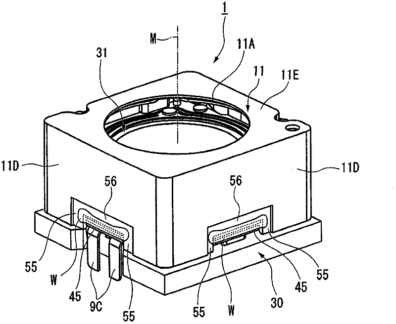
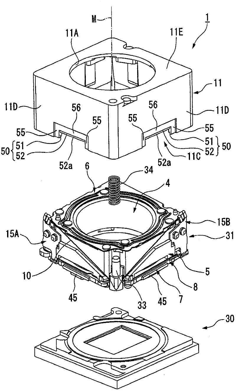
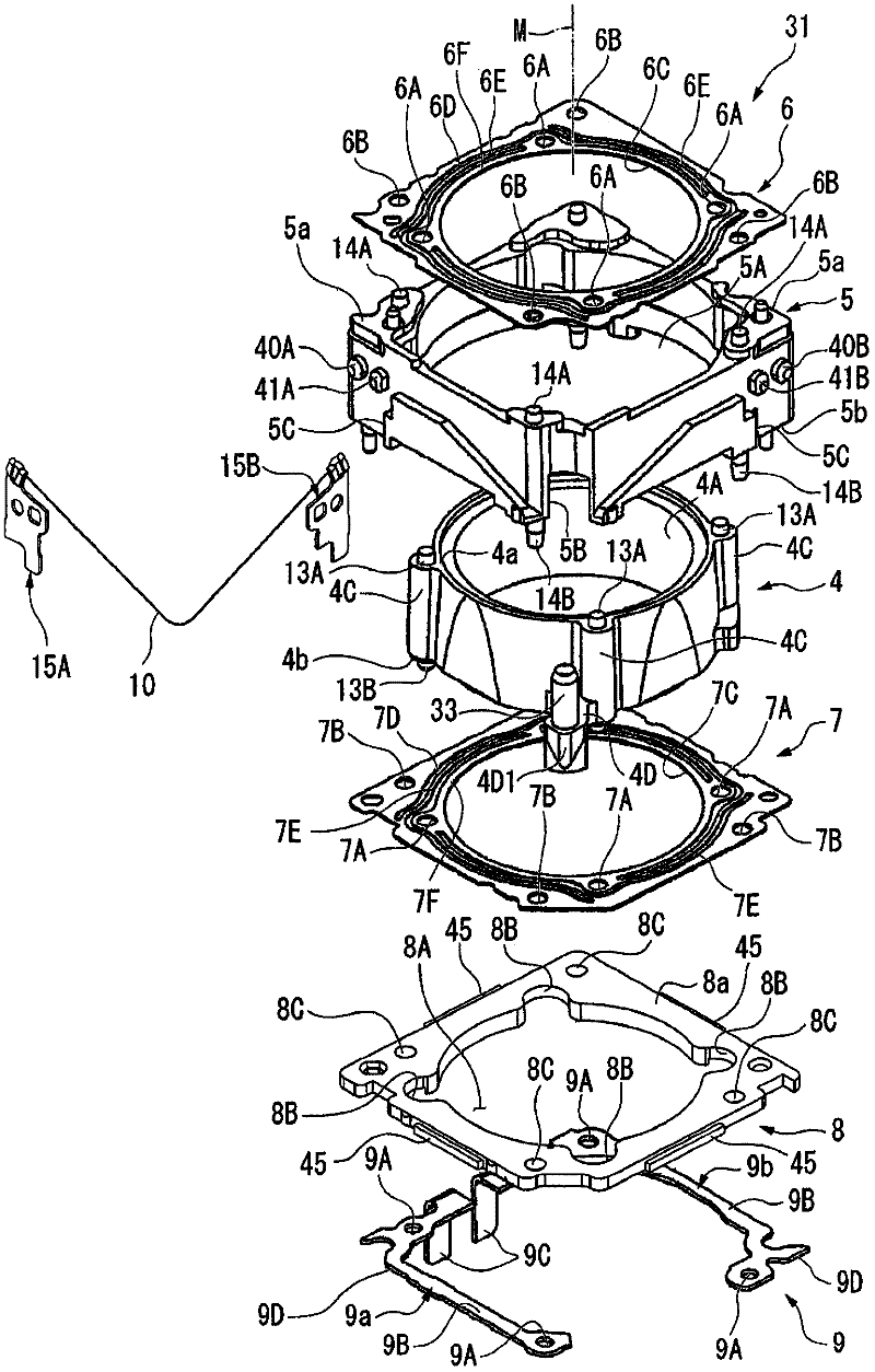
[0075] Below, refer to Figure 1 to Figure 16 , an embodiment of the drive module according to the present invention will be described. In addition, in this embodiment, a driving module that drives an imaging lens unit in a camera will be described as an example. In addition, as an example of an actuator that drives a lens unit, a case where a shape memory alloy wire is used will be exemplified.

[0076] In addition, in this embodiment, in some drawings, in order to make it easier to see, for example, the Figure 5 The shown lens unit 12 and other components are shown in the figure.

[0077] in addition, figure 1 Symbol M in the diagrams is a virtual axis line of the driving module 1 that coincides with the optical axis of the lens unit 12 , and indicates the driving direction of the lens frame 4 described later. Hereinafter, in the description of each disassembled component, the position or direction may be referred to based on the positional rel...


PUM


Abstract

A driving module 1 includes: a support member 5 fixed on a base substrate 8; a driven member 4 arranged so as to be movable back and forth in relation to the support member; driving means 10 for driving the driven member; and an exterior cover 11 attached so as to cover the support member, the driven member, and the driving means and attached and fixed to the base substrate. A projection piece 45 which is accommodated in a concave accommodation portion 50 is formed on the base substrate. The base substrate and the exterior cover are attached and fixed by an adhesive agent filled in a first filling region which is defined between a lateral inner wall 51 and the projection piece and a second filling region which is defined between an upper inner wall 52 and the projection piece. A lateral step portion 55 which is formed to be recessed in a state of being continuous to the lateral inner wall of the concave accommodation portion and to which the adhesive agent running out of the first filling region is guided is formed on the exterior cover.

Description

technical field [0001] The invention relates to drive modules and electronic equipment. [0002] In particular, it relates to a drive module and an electronic device suitable for driving an optical system or a movable member for focus position adjustment or as an actuator. Background technique [0003] Conventionally, various driving modules have been proposed, which use the shape memory alloy wire to perform self-focusing or zooming in order to drive a driven body such as an imaging lens unit in a small electronic device such as a camera-equipped mobile phone. It is driven by expanding and contracting (refer to Patent Document 1). [0004] The drive module described in Patent Document 1 includes: a support body fixed to the module lower plate; a lens frame capable of reciprocating in a certain direction relative to the support body; a leaf spring member elastically holding the lens frame; and a drive device , to drive the lens frame against the elastic restoring force of ...

Claims


Application Information

Patent Timeline
Patent Type & Authority Applications(China)
IPC IPC(8): G02B7/04G02B7/02
CPCB29C65/54G02B7/08B29C65/4855B29C65/606B29L2031/3481B29C66/74283B29C66/5346B29C66/81G02B13/001B29C65/18B29C66/742B29C65/08B29C66/304B29C66/322B29C66/54G02B7/025B29C65/48B29K2069/00B29K2105/0079
Inventor 小棚木进
Owner SEIKO INSTR INC
Why Eureka
Try Eureka