Conductor spacer rotation wire clip

A technology of spacer rods and rotary wires, which is applied in the direction of the device for maintaining the distance between parallel conductors and the mechanical vibration attenuation device. It can solve the problems of tower collapse, wire breakage, and inability to rotate relative to each other, so as to reduce maintenance and replacement and prolong service life. , to avoid the effect of sliding wear

Inactive Publication Date: 2012-03-21
GULIFA GRP CO LTD +1
View PDF5 Cites 5 Cited by
  • Summary
  • Abstract
  • Description
  • Claims
  • Application Information

AI Technical Summary

Problems solved by technology

In ice and snow weather, icing is easy to form on the overhead transmission line. Since the fixed holding between the spacer and the wire limits the twisting of the wire, the icing is often eccentric, forming an airfoil-shaped section, so that at a certain speed Under the excitation of strong wind, it will cause low-frequency and large-amplitude galloping in the line, resulting in flashover and tripping of the transmission line, damage to fittings and insulators, broken wires, and even accidents such as tower collapse.
The name of the invention is "Overhead Transmission Line Spacer Revolving Clamp", and the patent number is: ZL200520122172.2. The Chinese invention patent introduces a kind of overhead transmission line spacer revolving clamp, which is characterized in that the first clamp is used to hold the wire. And it is connected to the connection hole of the second clamp on the body of the spacer with the center of the conductor as the rotation, so the conductor can be rotated longitudinally to avoid eccentric ice coating, thereby achieving the purpose of preventing galloping of the transmission line, but due to the outside of the first clamp The surface and the inner surface of the second wire clip clamping hole are in direct contact when rotating, which is very easy to wear, and in ice and snow weather, the two wire clips are easily frozen into one and cannot rotate relative to each other, losing the anti-galling function

Method used


Image

  • Conductor spacer rotation wire clip
  • Conductor spacer rotation wire clip
  • Conductor spacer rotation wire clip

Examples


Embodiment Construction

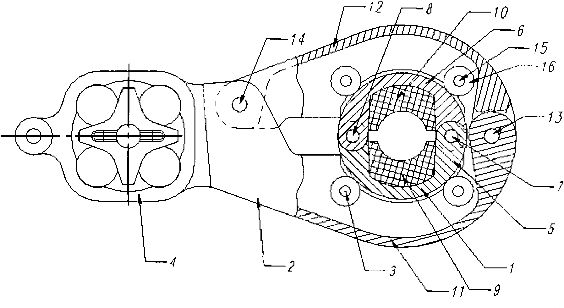
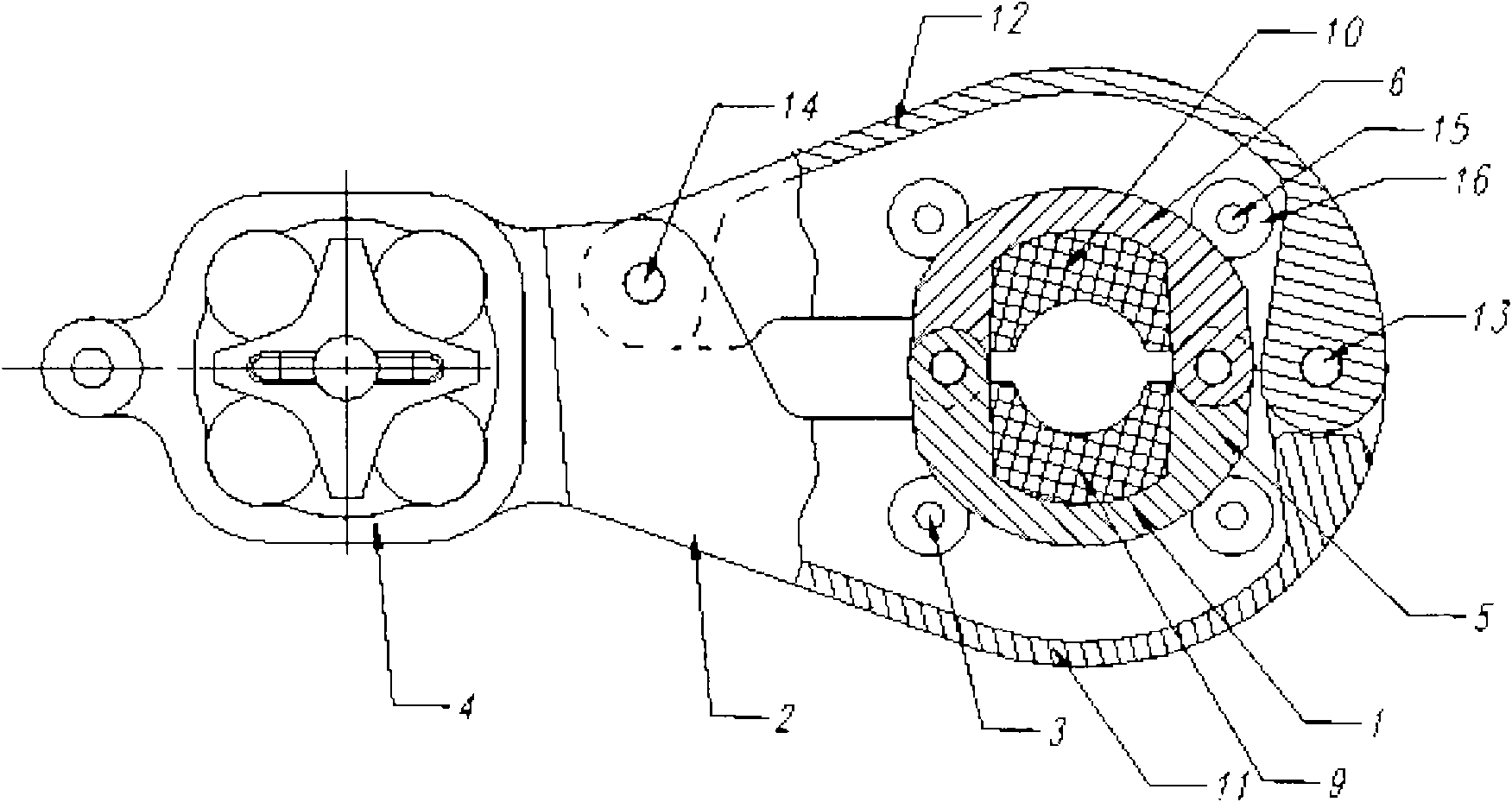
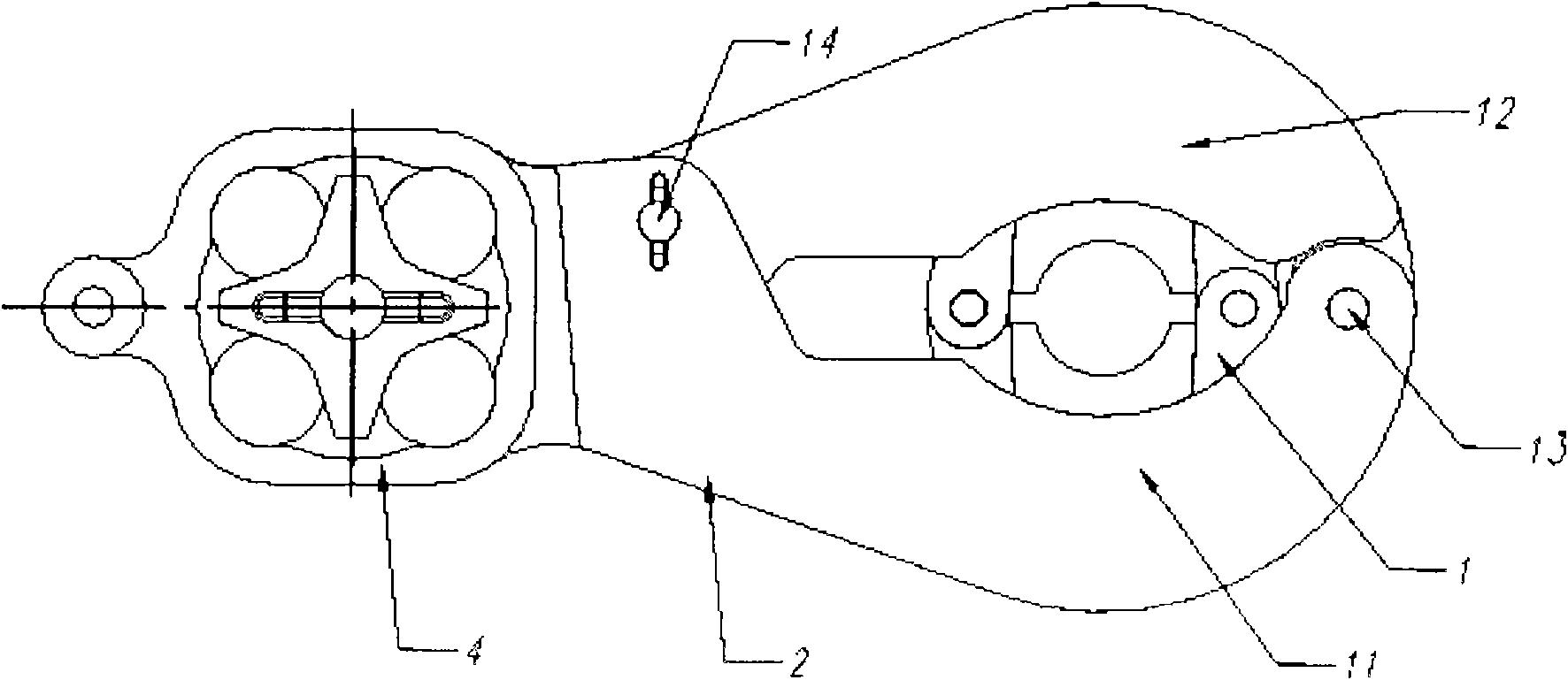
[0028] Now in conjunction with the preferred embodiment shown in the accompanying drawings, the structure of the present invention will be further described.

[0029] Depend on Figure 1-5 It can be seen that the spacer bar rotary clamp of the present invention is mainly composed of a center line clamp 1, a pincer arm 2 and several rollers 3. The center line clamp 1 is provided with a crimping groove for fixing and holding the wire. One end of the pincer arm 2 is a pincer buckle formed by two pincer clamps 11 and 12. The center line is fixed by several rollers 3 installed inside. The clamp 1 is fixed in the pincer buckle, and the center line clamp 1 can rotate around the wire in the pincer buckle of the pincer arm 2, so the wire clamped in it has a degree of freedom of rotation, so that the wire is eccentrically covered with ice. Under the eccentric force, the central line clamp 1 can be freely twisted, and eccentric icing cannot be formed in the end, so as to achieve the pur...


PUM


Abstract

The invention relates to a conductor spacer rotation wire clip which is used for spacing leads on an overhead transmission line, and mainly comprises a central wire clip, a tong-shaped arm and a plurality of rollers, wherein the central wire clip is provided with a wire pressing groove for fixing leads; one end of the tong-shaped arm is provided with a tong-shaped buckle; the central wire clip is fixed in the tong-shaped buckle through the plurality of rollers installed at the inner side, and can rotate in the tong-shaped buckle of the tong-shaped arm by taking the leads as the axis; and the other end of the tong-shaped arm has a handle-shaped structure, and can be connected with a spacer bracket. By adopting the conductor spacer rotation wire clip for an overhead transmission line, the leads clamped have rotation freedom and can twist freely along with the central wire clip under the eccentric force of eccentric ice coating, so that the eccentric ice coating can not be formed finally, and the aim of preventing the transmission line from waving can be achieved. Compared with the prior art, the central wire clip of the conductor spacer rotation wire clip and the tong-shaped arm are connected by adopting the rollers, and has the advantages of wear resistance, flexible rotation, hard freezing and the like.

Description

technical field [0001] The invention relates to a wire clip structure used on a spacer bar of an overhead transmission line, which belongs to a protective fitting for an electric power system, and is especially suitable for spaced support for split conductors in a high-voltage transmission line, and has a spacer bar for preventing galloping of an overhead transmission line Swivel clip. Background technique [0002] There are various spacers in the current overhead transmission lines, and the clamps and the conductors are fixedly held, which are mainly used to resist the centripetal force generated by the same-phase current of the conductors and maintain the distance between the sub-wires of the split conductors to reduce corona. Generates and dampens breeze vibrations on transmission lines. In ice and snow weather, icing is easy to form on the overhead transmission line. Since the fixed holding between the spacer and the wire limits the twisting of the wire, the icing is of...

Claims


Application Information

Patent Timeline
IPC IPC(8): H02G7/14H02G7/12
Inventor 郑哲
Owner GULIFA GRP CO LTD
Why Eureka
Try Eureka