Digital/analog converting device and method

A digital-to-analog conversion and conversion technology, applied in the field of digital-to-analog conversion devices, can solve problems such as increasing the overall area of ​​a current source structure, and achieve the effect of avoiding a large area

Active Publication Date: 2014-07-02
ALI CORP
View PDF4 Cites 0 Cited by
  • Summary
  • Abstract
  • Description
  • Claims
  • Application Information

AI Technical Summary

Problems solved by technology

First of all, in order to reduce the adverse effect caused by the mismatch of the sub-current source, it is necessary to increase the area of ​​the sub-current source to reduce the effect of mismatch, which will increase the overall area of ​​the current source structure
In addition, since the output current Io of the current source 50 is adjusted by switching the on or off state of the sub-current source, and at the moment of switching the sub-current source, a transient glitch (glitch power) is often generated.
[0006] Therefore, although the prior art has provided current source architectures that control the rise / fall times of signal transitions, there is still room for improvement.

Method used


Image

  • Digital/analog converting device and method
  • Digital/analog converting device and method
  • Digital/analog converting device and method

Examples


Embodiment Construction

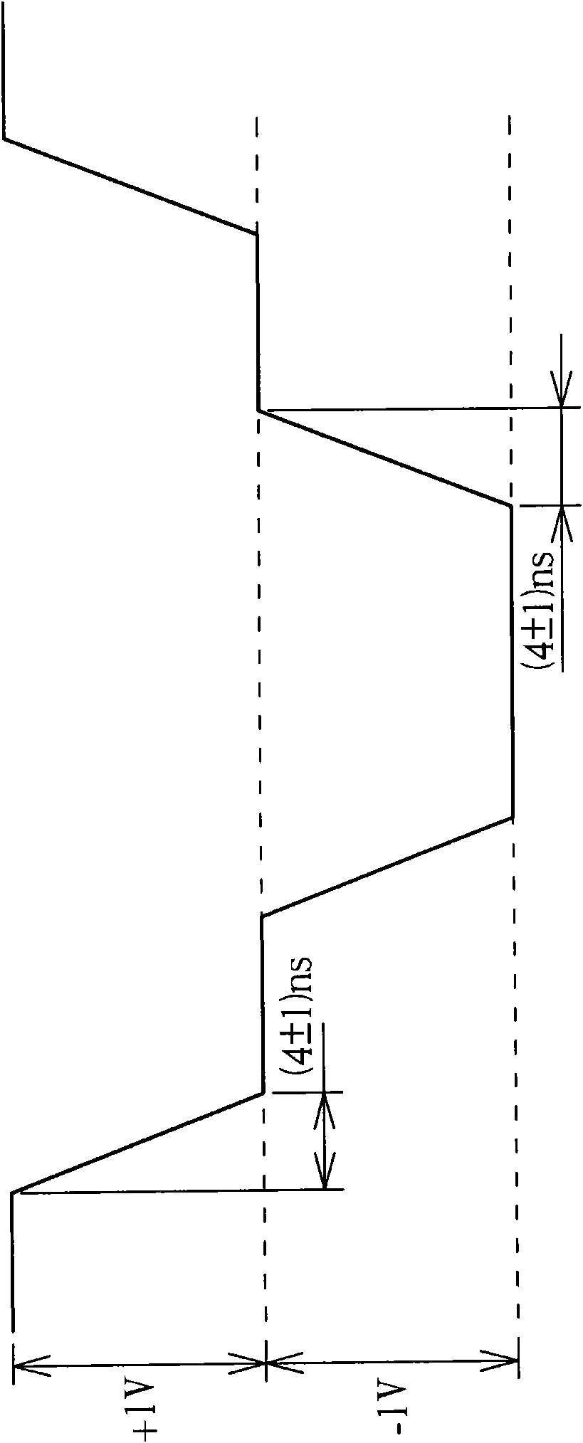
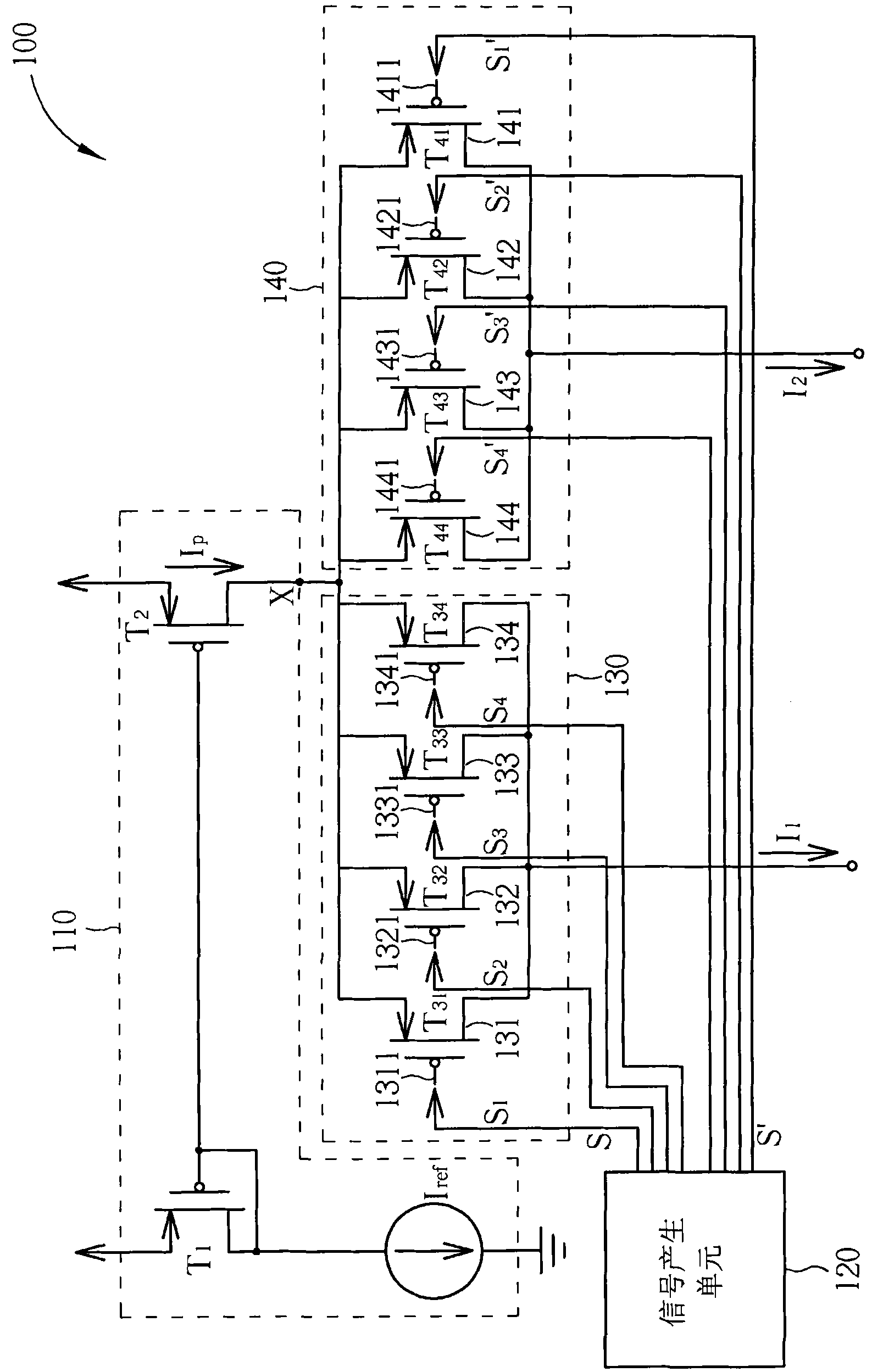
[0032] Please refer to image 3 , which is an embodiment of the current output device of the present invention. As shown in the figure, the current output device 100 includes a current source 110 , a signal generating circuit 120 and shunt circuits 130 , 140 . The current source 110 has an output terminal X, and outputs a supply current I P . In this embodiment, the current source 110 includes a current mirror circuit composed of a transistor T1 and a transistor T2, wherein the size ratio (W / L) of the transistor T2 is N times the size ratio (W / L) of the transistor T1, Therefore, the supply current I generated by the output terminal X of the current source 110 P will be the reference current I flowing through transistor T1 REF However, this is an embodiment of the present invention, not a limitation of the present invention; in other embodiments of the present invention, the current source 110 can also be implemented in a manner other than a current mirror circuit.

[0033...


PUM


Abstract

The invention discloses a digital / analog converting device and method. A current output device comprises a current source, a signal generation circuit and a plurality of shunt circuits, wherein the current source is used for outputting supply current; the signal generation circuit is used for respectively generating a first group of control output signals and a second group of control output signals; the shunt circuits comprise at least one first shunt circuit and at least one second shunt circuit; the first group of control output signals and the second group of control output signals are used for shunting the supply current so as to generate first shunt current and second shunt current; and the first shunt current and the second shunt current are used for generating an analog output signal, so that the change of the analog output signal is decided by the magnitudes of the first shunt current and the second shunt current.

Description

technical field [0001] The present invention relates to signal processing and signal waveform control, especially to a digital-to-analog conversion device and its related method, which can effectively control the rising / falling time of its output signal transition. Background technique [0002] Digital to analog converters are widely used in various electronic circuits. Generally speaking, the operation of digital to analog converters is to convert a digital input signal into an analog output signal. Since the digital-to-analog conversion device usually has to respond to signal transitions, the required rise / fall time of the digital-to-analog conversion device to generate an output signal becomes an important characteristic of the digital-to-analog conversion device. In most cases, the rise / fall time of the signal needs to be controlled within a reasonable time range to avoid adverse effects such as signal distortion caused by too long rise / fall time, while too short rise / fa...

Claims


Application Information

Patent Timeline
Patent Type & Authority Patents(China)
IPC IPC(8): H03M1/66
Inventor 许智渊蔡志厚
Owner ALI CORP
Why Eureka
Try Eureka