Gas cutting guiding device

A guiding device, gas cutting technology, applied in auxiliary devices, gas flame welding equipment, welding/cutting auxiliary equipment, etc., can solve the problems of increasing machine tool maintenance costs, influence of equipment machining accuracy, tool wear, etc., to facilitate large-scale investment Use, improve the efficiency of gas cutting work, the effect of low manufacturing cost

Active Publication Date: 2012-03-28
SHANGHAI BOILER WORKS
View PDF8 Cites 7 Cited by
  • Summary
  • Abstract
  • Description
  • Claims
  • Application Information

AI Technical Summary

Problems solved by technology

In addition, manual operation is adopted, the end face of the gas-cut pipe becomes jagged, and the surface shape is very poor
[0003] The gas-cutting end cap of the above-mentioned pipe takes longer in the process of groove re-boring, which will seriously affect the wear of the tool, especially the service life and machining accuracy of the equipment.
When processing such large-diameter pipe ports, the internal gears of the boring machine are constantly subjected to impact loads, which can easily cause gear breakage, increase the maintenance cost of the machine tool, and delay the manufacturing cycle of the product header
At the same time, the machining accuracy of the equipment will also be seriously affected

Method used


Image

  • Gas cutting guiding device
  • Gas cutting guiding device
  • Gas cutting guiding device

Examples


Embodiment Construction

[0023] The following combination Figure 1 ~ Figure 3 , a preferred embodiment of the present invention is described in detail.

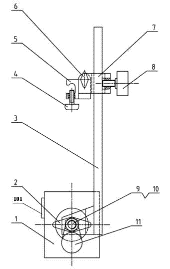
[0024] Such as figure 1 Shown is a schematic structural view of the gas cutting guide device in the present invention. The gas cutting guide device includes a clamping and positioning mechanism and a variable speed transmission mechanism 11; the clamping and positioning mechanism includes an end cover connecting guide mechanism and a gas cutting torch installation and positioning mechanism.

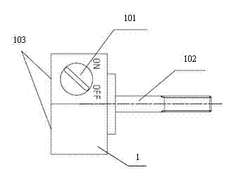
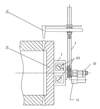
[0025] Wherein, the end cover connection guide mechanism includes a magnetic block 1 and a guide block 3 . Such as figure 2 As shown, the magnetic control switch 101 is installed on the magnetic block 1, the magnetic control switch 101 is turned on, and the magnetic adsorption area 103 of the magnetic block 1 can be controlled to have magnetism, so that the magnetic block 1 can be fixedly installed on the pipe end The end face of the cover 13; when the mag...


PUM


Abstract

The invention relates to a gas cutting guiding device which comprises a clamping locating mechanism and a speed-changeable transmission mechanism. The clamping locating mechanism comprises an end cover connection guiding mechanism and a gas cutting gun mounting locating mechanism, wherein the end cover connection guiding mechanism comprises a magnetic block and a guiding block, the magnetic block is fixedly arranged on the end surface of a pipe end cover, a threaded core shaft is arranged at the center of the end surface of the magnetic block, the guiding block is arranged on the threaded core shaft in a through manner and can rotate around the threaded core shaft. The speed-changeable transmission mechanism is arranged on the threaded core shaft of the magnetic block. The gas cutting gun mounting locating mechanism is arranged on the guiding block and comprises a locating block and a clamping device, wherein the locating block is arranged on the guiding block and can slide up and down along the guiding block, and the clamping block is connected with the locating block and can rotate around the locating block. The gas cutting guiding device disclosed by the invention can provide the gas cutting guiding for the pipe end covers with different diameters, and limits the axial drifting of a gas cutting gun and modifies the gas cutting end surface formation of pipes in an operation process of gas cutting the end cover; in addition, the universality is strong, the work efficiency is improved, and the large-scale investment and application of workshops is convenient.

Description

technical field [0001] The invention relates to a gas cutting processing tool for a metal pipe end cap, in particular to a gas cutting guide device for a metal pipe end cap. Background technique [0002] In the prior art, when the hydraulic pressure test of the boiler header is completed and the metal pipe hydraulic test end cover margin line is drawn, the gas cutting operator in the workshop uses a gas cutting gun to perform gas cutting operations on the header pump water end cover and the pipe joint. . If this method is used to remove the pump water end cover, a full circle of oxide layer with a certain thickness and extremely high hardness will be formed around the gas cutting opening at the end of the pipe. In addition, manual operation is adopted, and the end face of the gas-cut pipe becomes jagged, and the surface shape is very poor. [0003] The gas-cutting end cap of the above-mentioned pipe takes longer in the process of bevel re-boring, which will seriously affec...

Claims


Application Information

Patent Timeline
IPC IPC(8): B23K7/10
CPCB23K7/005B23K7/10B23K37/027B23K7/105
Inventor 陈力孙厚彬顾卫红辛炜
Owner SHANGHAI BOILER WORKS
Why Eureka
Try Eureka