Wheel-track switching motor-driven trolley for disaster rescue

A technology of electric trolleys and wheel shoes, which is applied in the direction of electric vehicles, motor vehicles, tracked vehicles, etc., can solve the problems of being unable to quickly adapt to the on-site environment and collect on-site information, not suitable for long-distance movement, and increasing the labor intensity of disaster relief personnel, etc.

Active Publication Date: 2012-12-12
WUHAN UNIV OF SCI & TECH
View PDF1 Cites 0 Cited by
  • Summary
  • Abstract
  • Description
  • Claims
  • Application Information

AI Technical Summary

Problems solved by technology

[0002] Due to the dangerous environment and complex terrain at the disaster relief site, the transportation of relevant materials and equipment is mostly carried out by manpower, which not only increases the labor intensity of disaster relief personnel, but also easily causes casualties and greatly reduces the efficiency of disaster relief
[0003] Although there are relatively mature highly integrated and highly intelligent robots in some disaster relief sites, which have greatly reduced the danger of disaster relief personnel and improved disaster relief efficiency, there are still some shortcomings in terms of usage: 1. In order to enhance Obstacle-surmounting ability, the walking system of the robot is generally designed with crawlers, which not only affects its movement speed, but also is not suitable for long-distance movement, and the disaster relief efficiency is not high; Second, the price is expensive, the structure is complicated, and the maintenance requirements are high, which is not conducive to popularization and application
[0004] A pneumatic remote control vehicle for firefighting (ZL 2010 2 0111766.4) is driven by an air motor, its movement speed is slow, and it cannot quickly adapt to the site environment and collect site information, which is not conducive to firefighters taking quick measures, and the work efficiency needs to be improved

Method used


Image

  • Wheel-track switching motor-driven trolley for disaster rescue
  • Wheel-track switching motor-driven trolley for disaster rescue
  • Wheel-track switching motor-driven trolley for disaster rescue

Examples


Embodiment Construction

[0092] The present invention will be further described below in conjunction with specific embodiment, is not the limitation of its protection scope:

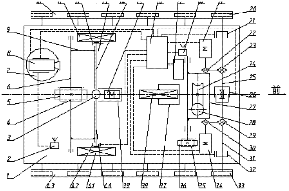
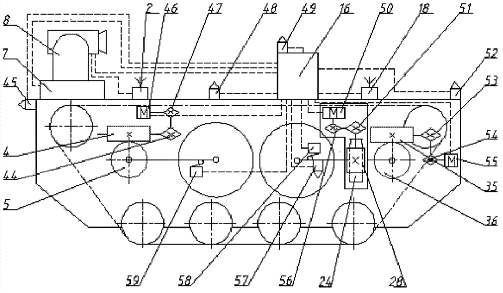
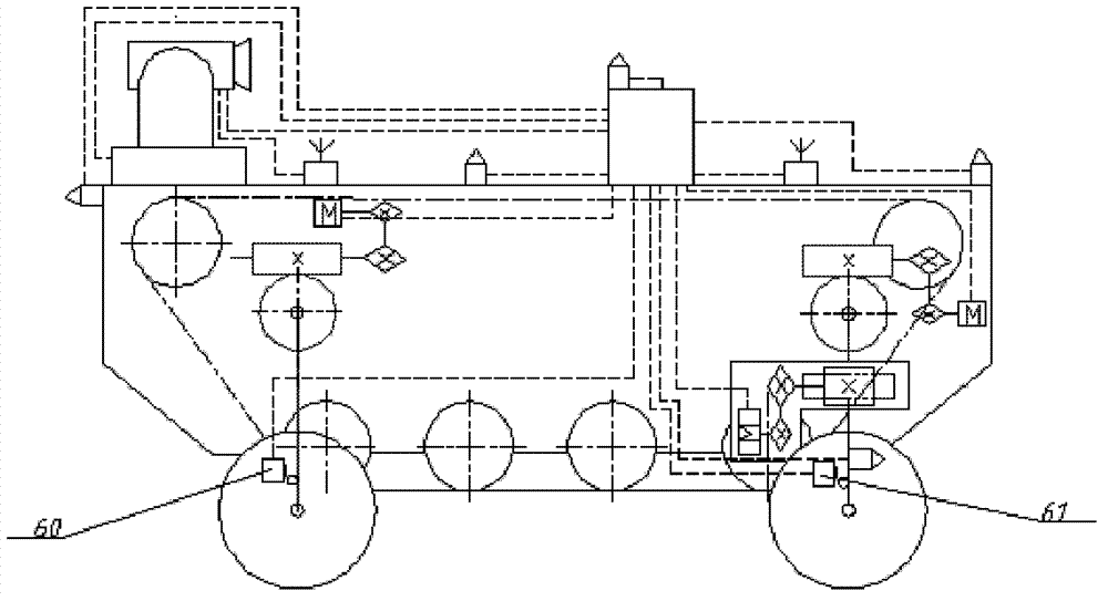
[0093] Disclosed is a wheel-shoe conversion electric trolley for disaster relief. The trolley includes a vehicle frame 1, a wheel system, a crawler drive system and a control system.

[0094] Frame 1 as Figure 4 Shown, be made up of upper floor vehicle frame 62, middle floor vehicle frame 63, lower floor vehicle frame 65 and 4 angle steels 64. The four corners of the middle frame 63 are respectively fixed in the middle of four angle steels 64, the upper frame 62 and the lower frame 65 are correspondingly fixed on the upper and lower ends of the four angle steels 64, the upper frame 62, the middle frame 63 and the lower frame 65 are parallel to each other, and the center lines of the upper floor vehicle frame 62, the middle floor vehicle frame 63 and the lower floor vehicle frame 65 are on the same vertical plane.

[0095] The ...


PUM


Abstract

The invention relates to a wheel-track switching motor-driven trolley for a disaster rescue. The technical scheme is as follows: terminal equipment (71) is connected with a vehicular wireless data transmission module (18) in a wireless manner so that a left side track drive motor (19) and a right side track drive motor (34) are controlled to drive a trolley to walk with tracks, a front landing gear drive motor (55) and a back landing gear drive motor (46) are controlled to realize mutual switch between the tracks and wheels, and a back wheel drive motor (15) and a turning motor (50) are controlled to realize wheel-type walk. A camera (8) is connected with a wireless video transmission module (2) so that wireless transmission of field images is realized. A front distance measurement sensor(52), a back distance measurement sensor (45), a trolley frame temperature sensor (48) and a control box temperature sensor (49) are respectively connected with a vehicular single chip computer (75) so that the trolley is ensured to work safely. The wheel-track switching motor-driven trolley has an all-terrain pass-through capacity and has the characteristics of real-time field condition display and long-distance remote control, is suitable for high-risk conditions of complex terrains and can be used for ensuring security of rescue workers.

Description

technical field [0001] The invention belongs to the technical field of disaster relief vehicles. In particular, it relates to a wheel-track converted electric trolley for disaster relief. Background technique [0002] Due to the dangerous environment and complex terrain at the disaster relief site, the transportation of relevant materials and equipment is mostly carried out by manpower, which not only increases the labor intensity of disaster relief personnel, but also easily causes casualties and greatly reduces the disaster relief efficiency. [0003] Although there are relatively mature highly integrated and highly intelligent robots in some disaster relief sites, which have greatly reduced the danger of disaster relief personnel and improved disaster relief efficiency, there are still some shortcomings in terms of usage: 1. In order to enhance Obstacle-surmounting ability, the walking system of the robot is generally designed with crawlers, which not only affects its mo...

Claims


Application Information

Patent Timeline
Patent Type & Authority Patents(China)
IPC IPC(8): B62D55/00B62D55/10B62D55/26B60L15/00
CPCY02T10/644Y02T10/64
Inventor 王兴东郑梅杰王强冒颖王世宇张安裕何涛徐占民
Owner WUHAN UNIV OF SCI & TECH
Why Eureka
Try Eureka