
High frequency image acquisition system for measuring flow rate

An image acquisition system and flow velocity measurement technology, which is applied in fluid velocity measurement, photogrammetry/video measurement, velocity/acceleration/shock measurement, etc., can solve the calculation error of flow velocity field and the inability to fully utilize the intensity of a single pulse light source and other problems, to achieve the effect of increasing the sampling speed, increasing the amount of light entering the machine, and improving the utilization rate

Inactive Publication Date: 2012-03-28
TSINGHUA UNIV
View PDF5 Cites 25 Cited by
  • Summary
  • Abstract
  • Description
  • Claims
  • Application Information

AI Technical Summary

Problems solved by technology

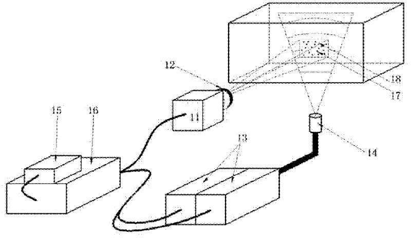
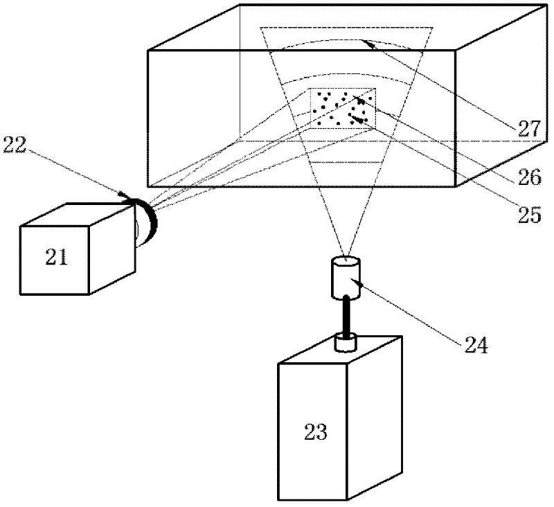
Therefore, the defect of fan-shaped sheet light is that the light source intensity of a single pulse cannot be fully utilized, because most of the light intensity does not pass through the shooting area; in addition, because the contour line of the sheet light intensity is arc-shaped, the measurement range is rectangular, namely The intensity of the image in the detection window parallel to the tank also changes with the direction of the water flow, which will bring errors to the calculation of the subsequent flow velocity field

Method used


Image

  • High frequency image acquisition system for measuring flow rate
  • High frequency image acquisition system for measuring flow rate
  • High frequency image acquisition system for measuring flow rate

Examples


Embodiment Construction

[0018] A high-frequency image acquisition system for flow velocity measurement of the present invention will be described in detail below with reference to the drawings and embodiments.

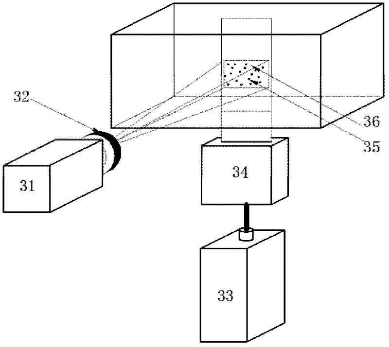
[0019] The high-frequency image acquisition system for flow velocity measurement proposed by the present invention, such as image 3 As shown, the system includes a high-speed camera 31, a lens 32, a continuous laser 33 and a combined lens 34; it is characterized in that the high-speed camera is equipped with a 50mm large-diameter interface, and the lens is a large-diameter aperture of F1.0 / 50mm The lens and the continuous laser adopt a low-power continuous laser with a maximum power of 2W-5W, and the combined lens adopts a set of combined lenses that convert the light beam emitted by the laser into a 1mm thick rectangular sheet of light.

[0020] The construction principle of the system of the present invention is:

[0021] According to the knowledge of optical imaging, the image quality ob...


PUM


Abstract

The invention relates to a high frequency image acquisition system for measuring a flow rate, and belongs to the technical field of water conservancy measurement. The system comprises a high speed camera, a lens, a continuous laser and a combination lens, and is characterized in that: the high speed camera is provided with a 50mm large-caliber lens adaptor; the lens has an F1.0 / 50mm large-caliberaperture; the continuous laser is a low-power continuous laser with the maximum power of 2-5W; and the combination lens can convert light beams emitted by the laser into 1mm-thickness rectangular plane light. The system can acquire images economically and safely at high frequency and high quality so as to continuously measure the flow rate of an open channel or a pipeline.

Description

technical field [0001] The invention belongs to the technical field of water conservancy measurement, in particular to high-frequency measurement of turbulent flow velocity field. Background technique [0002] The flow velocity of turbulent water flow has the randomness of spatial distribution and time continuity. In the development process of flow velocity measurement, from the traditional float ranging-timing method, pit tube, propeller current meter, to the modern electromagnetic flow meter, hot film (wire) flow meter, laser flow meter, etc. are all single-point measurement The ultrasonic flow meter can simultaneously measure the vertical distribution of the flow velocity; the particle image velocimetry technology PIV (Particle Image Velocimetry) developed in the past 30 years has realized the leap in the measurement of the instantaneous cross-sectional flow velocity field from point, line to surface, and is an important tool for experimental fluids. Mechanics provides a...

Claims


Application Information

Patent Timeline
IPC IPC(8): G01C11/00G01P5/20
Inventor 王兴奎钟强陈启刚李丹勋
Owner TSINGHUA UNIV
Learn More