
Infrared measuring method and device for end expiration CO2

A measuring device and measuring method technology, which are applied in the field of measuring gas concentration by infrared technology, can solve the problems of zero calibration affecting the real-time measurement, and the error varies greatly with temperature drift and voltage drift, so as to prolong the life, avoid measurement errors, The effect of improving stability

Active Publication Date: 2012-03-28
CONTEC MEDICAL SYST
View PDF6 Cites 12 Cited by
  • Summary
  • Abstract
  • Description
  • Claims
  • Application Information

AI Technical Summary

Problems solved by technology

Its frequent zero calibration affects the real-time performance of the measurement
And the error when not zeroing varies greatly with temperature drift and voltage drift

Method used


Image

  • Infrared measuring method and device for end expiration CO2
  • Infrared measuring method and device for end expiration CO2
  • Infrared measuring method and device for end expiration CO2

Examples


Embodiment 1

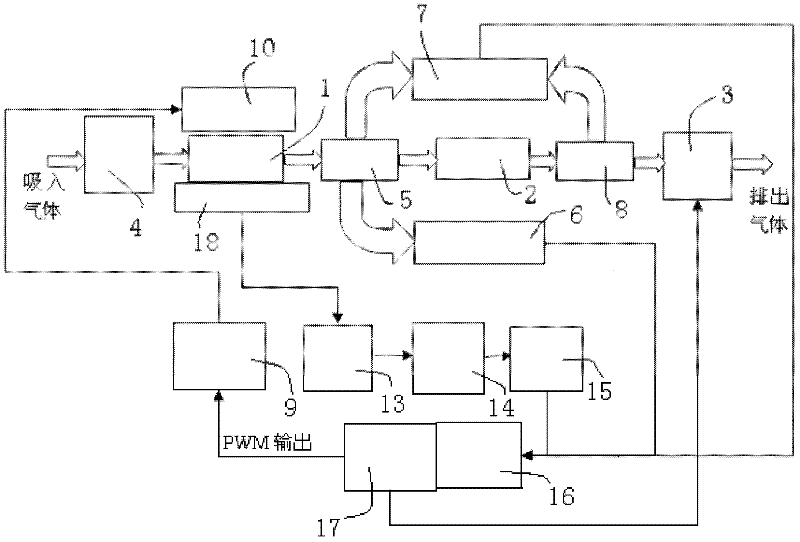
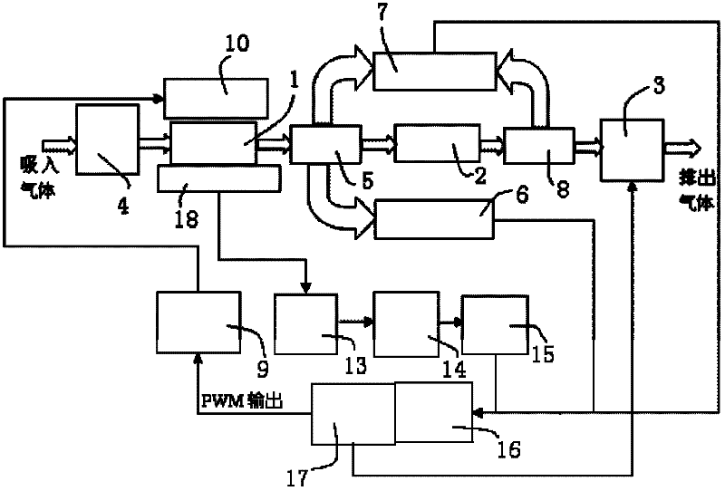
[0040] see figure 1 , an infrared end-tidal CO 2 Measuring device, including:

[0041] A gas circuit unit, including a single gas chamber 1, a throttle valve 2 and an air pump 3 connected in sequence, the gas to be measured is filtered through a throttle joint 4 before entering the single gas chamber 1, and the filtration grade of the throttle joint 4 is 5 μm ; The single air chamber 1 is connected with the throttle valve 2 through a four-way 5, and the throttle valve 2 and the air pump 3 are connected through a three-way 8;

[0042] An optical path unit, including a sequentially connected light source driving circuit 9 and an infrared light source 10, the infrared light source is an incandescent light source, and is arranged on one side of the single gas chamber 1;

[0043] An optical path and temperature detection unit, including a temperature sensor and a CO set on the opposite side of the single gas chamber 1 and the infrared light source 10 2 Infrared thermopile sensor...


PUM


Abstract

The invention relates to an infrared measuring method and device for end expiration CO2. The method comprises the following steps of: irradiating gas sealed in a single gas chamber by adopting an incandescent light source; making a signal of infrared light passing through the single gas chamber which is acquired by a CO2 sensor pass through an amplifying circuit; transmitting the signal into a processor through a filter circuit, a demodulating circuit and a digital-to-analogue converting module for processing; and compensating according to the pressure and the temperature to obtain the CO2 concentration of a sample to be measured. The device comprises a gas path unit, a light path and temperature detecting unit, a pressure detecting unit and a control unit. In the infrared measuring method and device for end expiration CO2, incandescence is taken as an infrared light source, and the filter circuit, the demodulating circuit and a temperature and pressure compensating system are arranged, so that measuring errors caused by aging of the light source, temperature drift and the voltage deviation of the amplifier in the infrared measuring process of end expiration CO2 in the prior art are avoided.

Description

technical field [0001] The invention relates to a method and a device for measuring gas concentration by using infrared technology, in particular to a method and device for measuring end-tidal CO by using infrared technology 2 Concentration methods and apparatus. Background technique [0002] Monitor patients' end-tidal CO with infrared principle 2 Concentration is a non-invasive monitoring method. It can not only monitor the patient's ventilation function but also reflect its circulatory function and pulmonary blood flow. It has become a commonly used clinical monitoring method. Patient's ventilatory function; monitor circulatory function and CO 2 Changes in output; understand changes in alveolar dead space and pulmonary blood flow; when patients are under general anesthesia or using a ventilator, the ventilation can be adjusted according to monitoring to avoid hyper- or hypocapnia caused by hypoventilation or over-ventilation; timely detection of mechanical problems of t...

Claims


Application Information

Patent Timeline
IPC IPC(8): G01N21/35G01N21/3504
Inventor 胡坤高瑞斌雷蕾
Owner CONTEC MEDICAL SYST
Learn More