Light source device and projector adopting same

A light source device and light source technology, which is applied to components of lighting devices, lighting devices, projection devices, etc., can solve the problems of complexity, long optical path, and high energy consumption of light source devices, and achieve energy loss avoidance, energy consumption reduction, and simple structure Effect

Inactive Publication Date: 2012-03-28
HISENSE
View PDF13 Cites 26 Cited by
  • Summary
  • Abstract
  • Description
  • Claims
  • Application Information

AI Technical Summary

Problems solved by technology

More optical components are not conducive to the simplification of the structure of the light source device, but also increase the cost of the light source device
[0011] In addition, because the blue light b needs to pass through two reflectors before reaching the exit position, the optical path is long and complicated, resulting in a large energy loss of the blue light b, resulting in high energy consumption of the light source device

Method used


Image

  • Light source device and projector adopting same
  • Light source device and projector adopting same
  • Light source device and projector adopting same

Examples


Embodiment 1

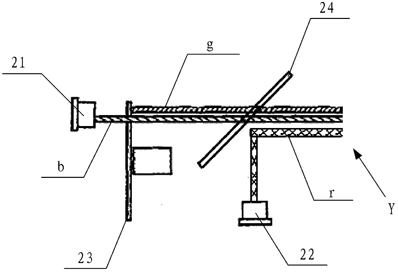
[0028] This embodiment provides a light source device, such as figure 2 As shown, the light source device includes: a blue semiconductor laser 21 , a red light source 22 , a transmissive fluorescent plate 23 and a dichroic mirror 24 .

[0029] Wherein, the transmissive fluorescent plate 23 such as Figure 4 As shown, there are formed: a transmission region 41 through which the blue light generated by the blue light semiconductor laser passes and a green phosphor region 42 excited by the blue light to generate and transmit green light. The area ratio of the two regions can be chosen according to the white balance and the energy requirements of the resulting light source. Of course, the transmissive fluorescent plate 23 is not limited to Figure 4 The circular plate shown can be a square plate, or other shapes known to those skilled in the art, and each zone is not limited to being distributed along the circumferential direction, and can also be other distribution methods kno...

Embodiment 2

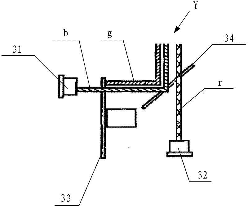
[0051] This embodiment also provides a light source device, such as image 3 As shown, the light source device and figure 2 The light source device shown has the same composition, including: a blue semiconductor laser 31 , a red light source 32 , a transmissive fluorescent plate 33 and a dichroic mirror 34 .

[0052] Wherein, the transmissive fluorescent plate 23 such as Figure 4 As shown, there are formed: a transmission region 41 through which the blue light generated by the blue light semiconductor laser passes and a green phosphor region 42 excited by the blue light to generate and transmit green light. The area ratio of the two regions can be chosen according to the white balance and the energy requirements of the resulting light source. Of course, the transmissive fluorescent plate 23 is not limited to Figure 4 The circular plate shown can be a square plate, or other shapes known to those skilled in the art, and each zone is not limited to being distributed along t...

Embodiment 3

[0065] This embodiment provides a projector, which includes the light source device described in Embodiment 1 or Embodiment 2, where the light source device is used to provide a light source for a display device in the projector.

[0066] Since the projector provided in this embodiment adopts the light source device described in Embodiment 1 or Embodiment 2, the production cost and energy consumption are reduced.

[0067] The embodiments of the present invention are mainly applied to occasions such as televisions, miniature projections, commercial and entertainment systems, and the like.


PUM


Abstract

The invention discloses a light source device and a projector adopting the same, which relate to the technical field of laser display and solve the problems that the existing light source device is complicated in structure, high in cost and higher in energy consumption. In the embodiment of the invention, as the light source device adopts a transmission type fluorescence plate, green rays generated by exciting green emitting phosphor by blue laser can transmit the transmission type fluorescence plate, and runs along the direction the same with the running direction of the blue laser transmitting the transmission type fluorescence plate, so that the running directions of blue rays and the green rays transmitting the transmission type fluorescence plate can be the same with that of red rays by only one dichroic mirror, thereby simplifying the structure of the light source device; and after transmitting the transmission type fluorescence plate, the blue rays can reach a emitting position by passing by the only one dichroic mirror, thereby greatly shortening an optical path and avoiding larger energy loss so as to reduce the energy consumption of the light source device.

Description

technical field [0001] The invention relates to the technical field of laser display, in particular to a light source device and a projector using the same. Background technique [0002] Laser display technology uses red lasers, green lasers, and blue lasers as light sources to reproduce the rich colors of the objective world. Among them, each color of laser light can be generated by a semiconductor laser. [0003] At present, the technology of green semiconductor lasers is not yet mature. If a green semiconductor laser is used as a green light source, serious speckle will be generated, which will affect the quality of the display image. The above-mentioned speckle problem is solved by using the principle that a blue semiconductor laser excites a green phosphor to generate green light. [0004] figure 1 It is a schematic diagram of an existing light source device based on the principle that a blue semiconductor laser excites a green phosphor to generate green light. [00...

Claims


Application Information

Patent Timeline
Patent Type & Authority Applications(China)
IPC IPC(8): G03B21/20G02B27/10F21V13/00
Inventor 李巍田有良闫国枫陈昱
Owner HISENSE
Why Eureka
Try Eureka