An ultra-wideband antenna and terminal

An ultra-wideband antenna and antenna technology, applied in antennas, resonant antennas, antenna components, etc., can solve problems such as narrow coverage and increased demand for parasitic structure space, and achieve reduced use of space, good impedance matching, and optimized ultra-wideband work The effect of the characteristic

Active Publication Date: 2016-09-28
ZTE CORP
View PDF5 Cites 0 Cited by
  • Summary
  • Abstract
  • Description
  • Claims
  • Application Information

AI Technical Summary

Problems solved by technology

However, with the increase of mobile communication modes, the expansion of mobile terminal frequency bands, and the development of data services, the above-mentioned methods have serious bottlenecks. Not only the bandwidth coverage is narrow, but the space requirements of the parasitic structure are further increased. Realized on ultra-thin and ultra-thin mobile terminals

Method used


Image

  • An ultra-wideband antenna and terminal
  • An ultra-wideband antenna and terminal
  • An ultra-wideband antenna and terminal

Examples


Embodiment Construction
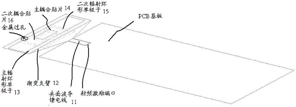
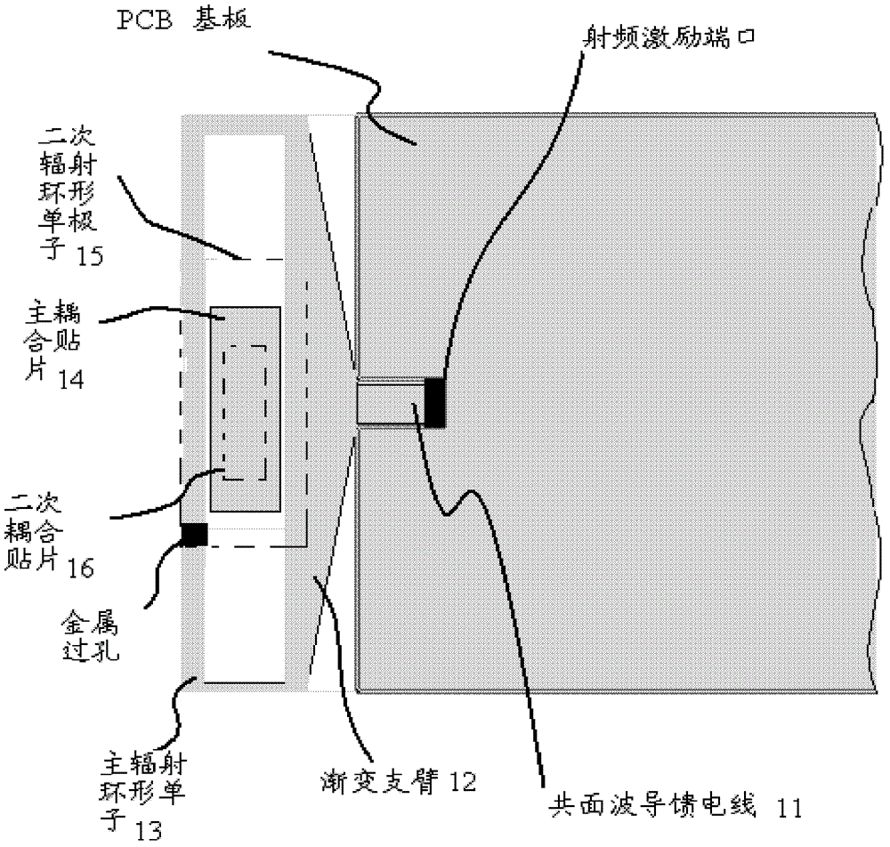
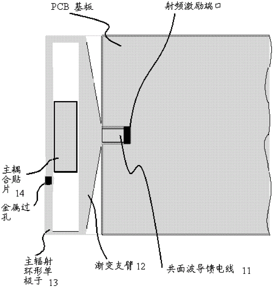
[0036] The basic idea of ​​the present invention is: the tapered arm and the coplanar waveguide feeder transmit the current of the RF excitation port to the main radiation ring monopole, and the main radiation ring monopole forms a coupling with the main coupling patch; at the same time, the main radiation ring The monopole transmits the current to the secondary radiating annular monopole through the metal via, and the secondary radiating monopole forms a coupling with the secondary coupling patch.

[0037] The present invention will be described in detail below through specific embodiments and accompanying drawings.

[0038] An ultra-wideband antenna such as figure 1 and figure 2 As shown, the device includes: a main radiating annular monopole 13, a main coupling patch 14, a tapered arm 12, a coplanar waveguide feeder 11, a secondary radiating annular monopole 15, and a secondary coupling patch 16; figure 2 For top view.

[0039] Among them, the main radiating annular mo...


PUM


Abstract

The invention discloses an ultra-wideband antenna, a coplanar waveguide feeder, one end of which is connected to a radio frequency excitation port of a PCB substrate, and one end connected to a gradient arm; one end of the gradient arm is connected to a coplanar waveguide feeder, and the other end is connected to a main radiation ring The monopole is connected; the main radiating ring monopole is connected with the gradient arm; the main coupling patch is located in the middle of the main radiating ring monopole; the secondary radiating ring monopole is connected to the main radiating ring monopole through a metal via The sub-connected; the secondary coupling patch is located in the middle of the secondary radiating ring monopole. The invention also discloses an ultra-wideband terminal. Using the antenna and the terminal described in the invention reduces the space used, facilitates the ultra-thinning of the terminal, widens the frequency band, and enables the terminal to work in the ultra-wideband range.

Description

technical field [0001] The invention relates to the field of antennas, in particular to an ultra-wideband antenna and a terminal. Background technique [0002] With the development of the world economy, mobile communication is constantly evolving from the third generation to the fourth generation, and the demand for multi-mode, multi-band, and multi-system mobile terminals is becoming stronger and stronger, such as world-mode mobile phones, data cards, etc., as mobile The front-end antenna of the terminal, how to achieve omni-directional coverage of 0.8GHz-5.5GHz ultra-broadband with a single antenna in a compact space, so as to save the space and cost of the mobile terminal, which is conducive to the miniaturization and ultra-thin development of the mobile terminal. The design of the antenna has a great test. [0003] At present, the widening antenna frequency band technology is mainly limited to the improvement of planar inverted F antenna (PIFA), inverted F antenna (IFA)...

Claims


Application Information

Patent Timeline
Patent Type & Authority Patents(China)
IPC IPC(8): H01Q1/38H01Q1/22H01Q5/25H01Q5/378
CPCH01Q5/25H01Q1/243H01Q1/38H01Q5/378H01Q9/40H01Q9/42
Inventor 陈亚军程守刚沈俊秦宇
Owner ZTE CORP
Why Eureka
Try Eureka