Light-source device
A technology of a light source device and a luminous tube, which is applied in the direction of light sources, electric light sources, point light sources, etc., can solve problems such as short faults, displacement of discharge tube 99, capacitive coupling loss, etc., and achieve the effect of low manufacturing cost
- Summary
- Abstract
- Description
- Claims
- Application Information
AI Technical Summary
Problems solved by technology
Method used
Image
Examples
Embodiment 1
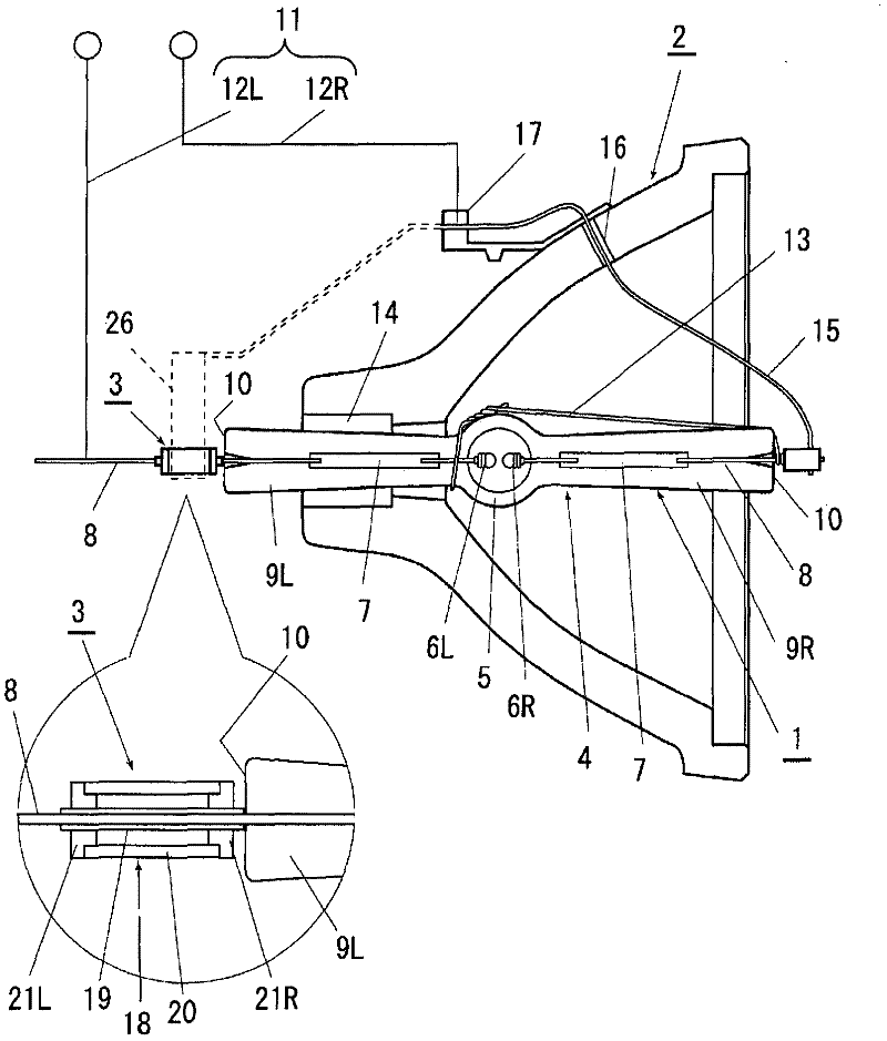
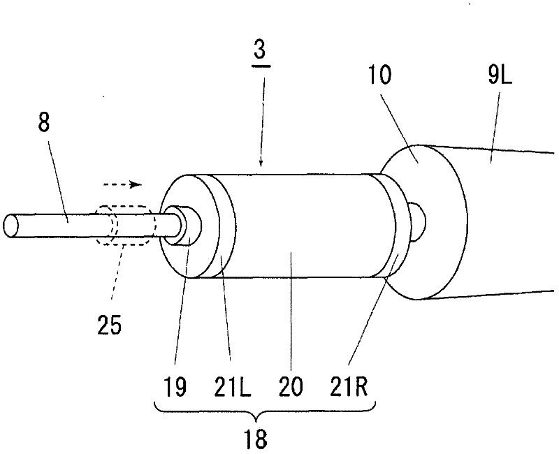
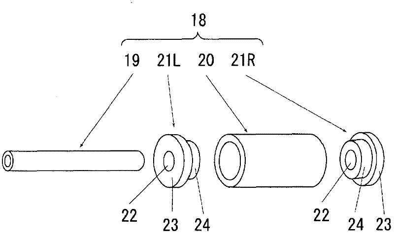
[0039] figure 1 It is a figure which shows an example of the light source device of this invention, figure 2 is a perspective view of the auxiliary light source activated by the light source device, image 3 is an exploded view showing the structural components for activating the auxiliary light source, figure 1 The light source device includes: a high-pressure discharge lamp 1; a concave reflector 2 that reflects light emitted from the lamp 1; and an auxiliary starting light source 3 that generates ultraviolet rays that improve the starting performance of the lamp 1.
[0040] In the high-pressure discharge lamp 1, a pair of tungsten wire electrodes 6R and 6L are arranged facing each other with a short pitch of about 1 mm in the discharge vessel 5 formed in the center of the arc tube 4 made of quartz glass, and mercury and bromine are enclosed. Start-up gases such as halogen and argon, etc., hermetically seal the part from the discharge vessel 5 to both ends of the arc tu...
Embodiment 2
[0053] Figure 4 It is a cross-sectional view showing a modified example of the activation auxiliary light source. The activation auxiliary light source 30 shown in this figure is provided with a pipe portion 32 penetrating through the center of a ceramic airtight container 31 filled with a rare gas such as argon. The airtight container 31 is formed by a cone-shaped container body 33 and a pair of large and small opening covers 34R and 34L that close the openings at both ends of the container main body. Holes 35, 35 of the same diameter at the center of , 34L.
[0054] Such as Figure 4As shown in (a), with regard to starting the auxiliary light source 30, the airtight container 31 will be sealed with an opening cover 34R having the same size as the end face 10 of the electrode sealing portion 9L or greater than or equal to the size of the end face 10 of the electrode sealing portion 9L. The large-diameter part side of the electrode seal part 9L faces the end face 10, and th...
Embodiment 3
[0057] Figure 5 (a) is an exploded perspective view showing a modified example of starting the auxiliary light source, and this figure (b) is a cross-sectional view thereof. Regarding the starting auxiliary light source 36 shown in this figure, the container main body 38 of the double-layer cylinder structure and the inner cylinder 40 The other end of the other end is inserted into the hole 42 and the opening cover 41 that closes the opening of the other end side of the outer cylinder 39 constitutes an airtight container 37 made of ceramics filled with a rare gas such as argon. The main body 38 is integrated by connecting one end of the outer cylinder 39 and one end of the inner cylinder 40 to close one end of the outer cylinder 39, and the inner cylinder 40 provided to penetrate the center of the container main body 38 becomes figure 1 The tube portion of the electrode lead 8 protruding from the end surface 10 of the electrode sealing portion 9L is inserted therethrough.
...
PUM
 Abstract
Description
Claims
Application Information
 - R&D
- Intellectual Property
- Life Sciences
- Materials
- Tech Scout
- Unparalleled Data Quality
- Higher Quality Content
- 60% Fewer Hallucinations
Browse by: Latest US Patents, China's latest patents, Technical Efficacy Thesaurus, Application Domain, Technology Topic, Popular Technical Reports.
© 2025 PatSnap. All rights reserved.Legal|Privacy policy|Modern Slavery Act Transparency Statement|Sitemap|About US| Contact US: help@patsnap.com


