
Semiconductor process processing system and method

A technology for processing systems, semiconductors, applied in the field of defective systems, capable of solving problems such as breakage, wafer breakage, wafer bending, etc.

Active Publication Date: 2012-04-04
TAIWAN SEMICON MFG CO LTD
View PDF10 Cites 0 Cited by
  • Summary
  • Abstract
  • Description
  • Claims
  • Application Information

AI Technical Summary

Problems solved by technology

Improper application of tape can lead to wafer breakage during the backgrinding process
Using TSVs, applying undue pressure on the adhesive and carrier wafer can again cause issues like wafer bow and breakage during backgrinding

Method used


Image

  • Semiconductor process processing system and method
  • Semiconductor process processing system and method
  • Semiconductor process processing system and method

Examples


Embodiment Construction

[0038] The following describes embodiments of systems and methods for reducing the generation of defects in semiconductor wafer processing in preparation for a backgrind tape die attach process. The "an embodiment" or the specific features mentioned in the "embodiment" in the description do not mean that this embodiment is only related to the single embodiment described, but its implementation can be shown in the description. In at least one embodiment. Similar technical features generally use similar index numbers, but it does not mean that each embodiment must have the same technical features. In addition, the technical features described in the drawings are not drawn according to specific dimensions, so specific dimensions should not be used to limit the features described in this system.

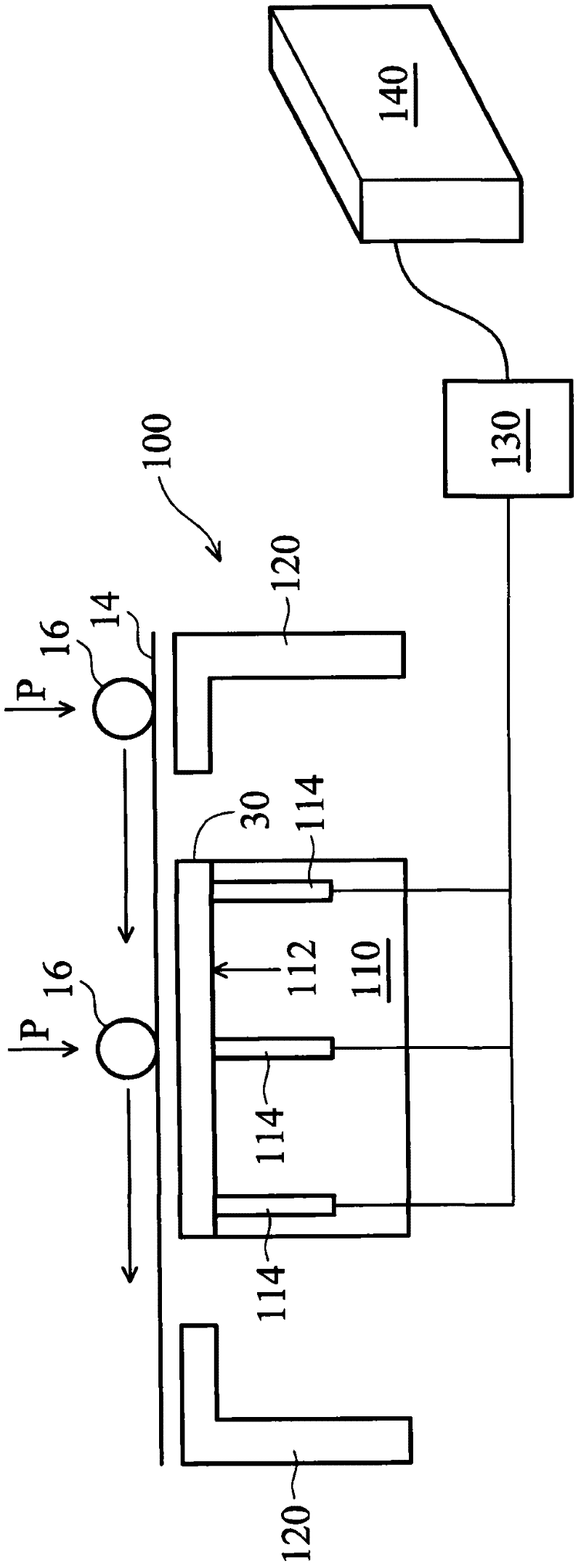
[0039] figure 1 A high level diagram is shown of a flip chip ball grid array system 100 according to an embodiment of the present invention for reducing defects in chip scale packaging...


PUM


Abstract

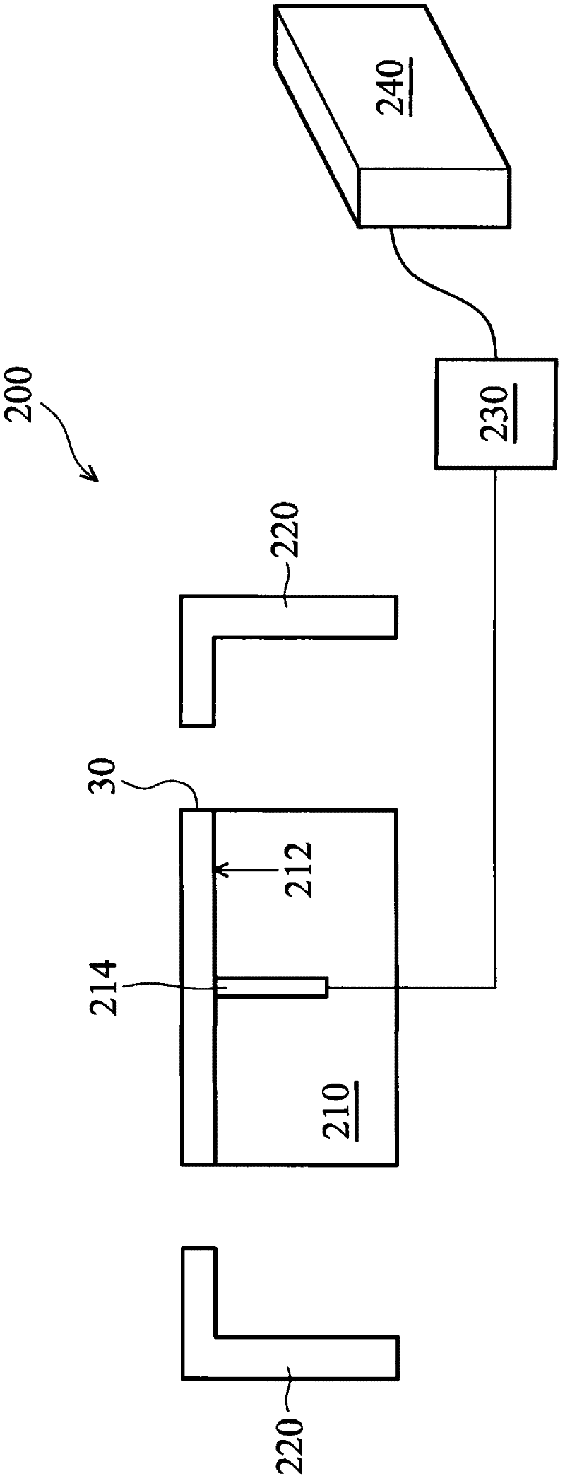
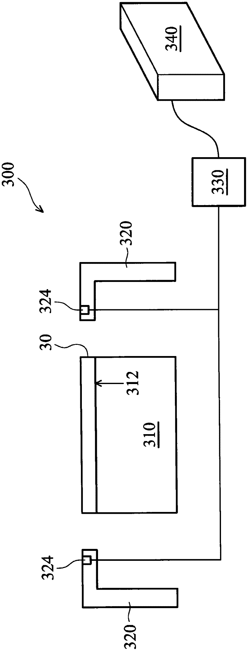
The present invention provides a semiconductor process processing system and a method, wherein processing defects arising during processing of a semiconductor wafer prior to back-grinding are reduced with systems and methods of sensor placement. The system comprises one or more holes bored into a chuck table for receiving semiconductor wafers; or a support table next to the chuck table; one or more sensors disposed in the holes for monitoring parameters during a pre-back-grinding (PBG) process; a control box converting a set of signals received from the sensors; a computer-implemented process control tool receiving the converted set of signals from the control box and determining whether the PBG process will continue.

Description

technical field [0001] The present specification generally relates to systems and methods for ameliorating defects in semiconductor wafer backgrinding processes. Background technique [0002] As the size of semiconductor devices continues to shrink, many design challenges will be faced. Processes to accommodate this trend use a very thin wafer in the manufacture of integrated circuits. Some current solutions in the semiconductor industry use backgrinding of integrated circuit wafers (also classified as semiconductor wafers) to reduce their thickness. This embodiment relates to the completion of the front or active side of the wafer and subsequent removal of excess substrate from the back of the wafer. [0003] After the active circuitry is formed on the front side of the wafer, one of two processing methods occurs. If a Flip Chip ball grid array (FCBGA) wafer process is used, according to this method, the circuit is covered with a laminating tape and followed by a back gr...

Claims


Application Information

Patent Timeline
IPC IPC(8): B24B37/04
CPCB24B37/04G05B19/41875B24B37/005
Inventor 卢祯发陈正庭胡毓祥刘重希
Owner TAIWAN SEMICON MFG CO LTD
Learn More