
Chemical mechanical polishing equipment

A technology of chemical machinery and equipment, applied in the field of semiconductor manufacturing technology, can solve the problems of shortened life, reduced reliability of semiconductor devices, metal short circuit, etc., to achieve the effect of ensuring yield, avoiding short circuit or failure, and ensuring reliability and life

Inactive Publication Date: 2012-04-04
SEMICON MFG INT (SHANGHAI) CORP
View PDF3 Cites 11 Cited by
  • Summary
  • Abstract
  • Description
  • Claims
  • Application Information

AI Technical Summary

Problems solved by technology

Therefore, abrasive particle clusters and other impurities form pollutants that affect the quality of wafer grinding. If these pollutants are not removed in time, more serious scratches may occur on the surface of the wafer.
These small and hard-to-find microscratches on the surface of the wafer cause hidden areas in the deposition technology, which may cause short circuits or failures between the same layer of metal, affect the final yield of the wafer, and lead to a reduction in the reliability and life of semiconductor devices shortening of

Method used


Image

  • Chemical mechanical polishing equipment
  • Chemical mechanical polishing equipment
  • Chemical mechanical polishing equipment

Examples


no. 1 example

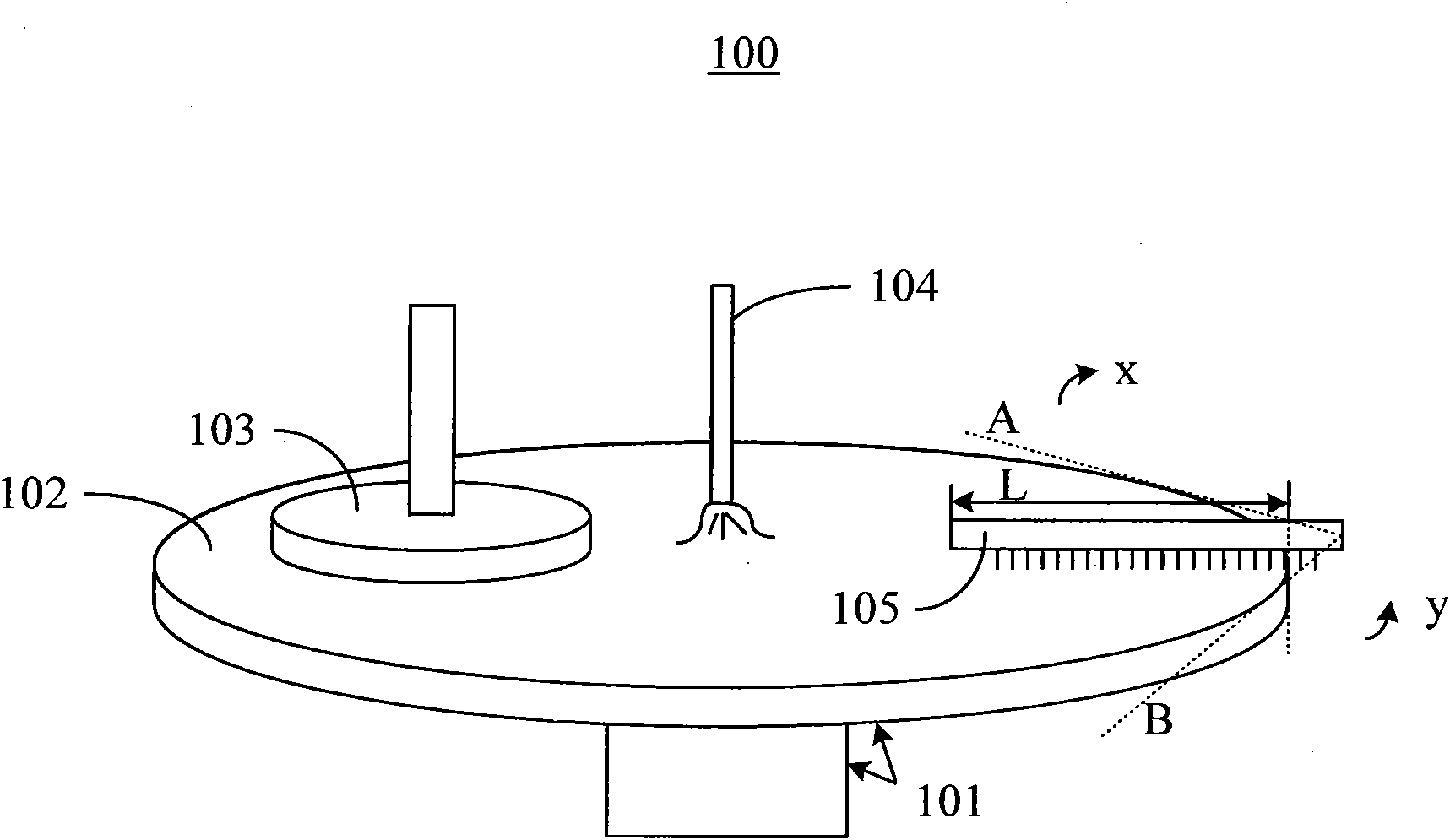
[0027] Such as figure 1 As shown, the chemical mechanical polishing equipment 100 comprises a rotary table 101, a polishing pad 102 fixed on the surface of the rotary table 101, a polishing head 103 for fixing the wafer and pressing the wafer on the surface of the polishing pad 102, and spraying the polishing slurry on the surface of the polishing pad 102. Abrasive spray head 104, abrasive pad cleaning member 105 and drive components (not shown). The chemical mechanical polishing equipment 100 grinds the wafer through the relative movement between the rotary table 101 and the polishing head 103 under the action of the polishing slurry. Since the chemical mechanical polishing equipment 100 described here has a similar structure and component composition with the widely used chemical mechanical polishing equipment, except for the polishing pad cleaning part 105 and the driving part (not shown), for the sake of simplicity, the General components such as the rotary table 101 , th...

no. 2 example

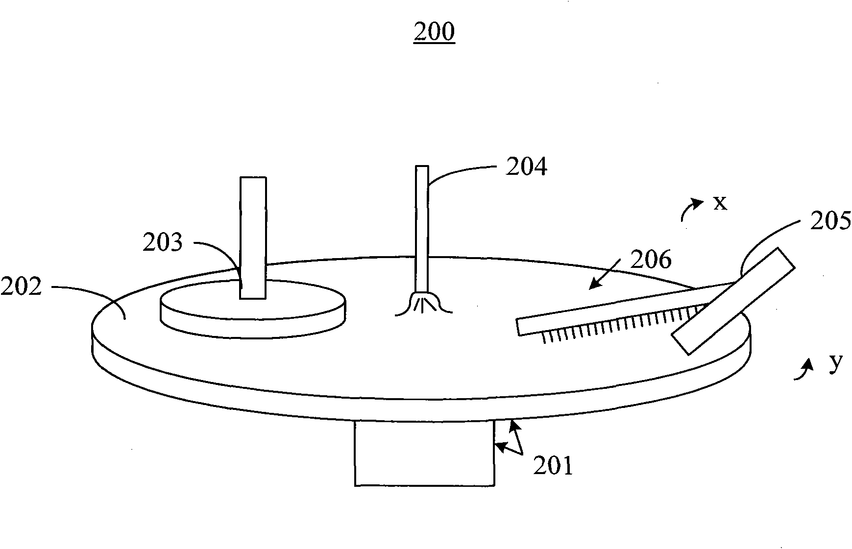
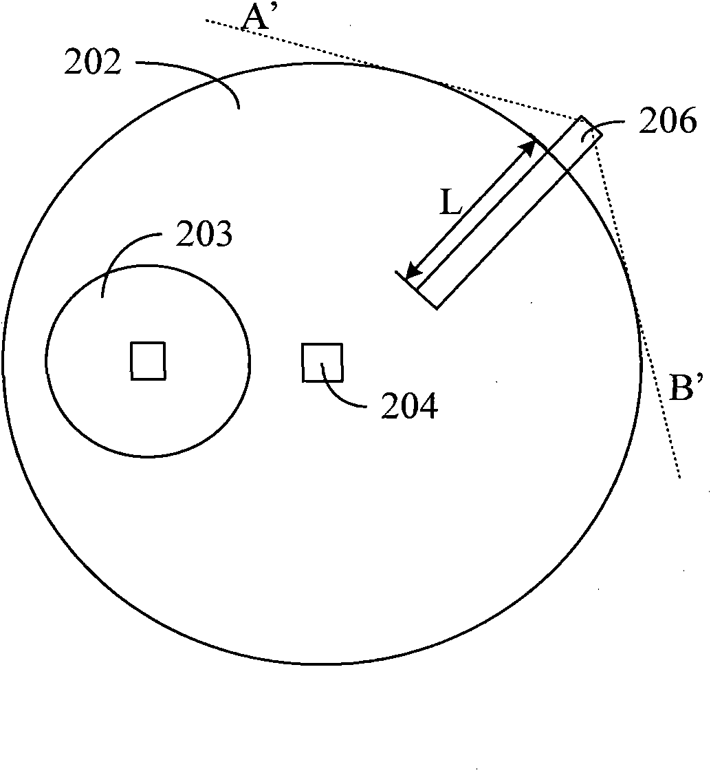
[0036] Such as Figure 2A As shown, the chemical mechanical polishing equipment 200 includes a rotary table 201, a polishing pad 202 fixed on the surface of the rotary table 201, a polishing head 203 for fixing the wafer and pressing the wafer on the surface of the polishing pad 202, and spraying the polishing slurry on the surface of the polishing pad 202. Abrasive spray head 204, pad conditioning arm 205, pad cleaning member 206 and drive components (not shown). The chemical mechanical polishing equipment 200 polishes the wafer through the relative movement between the rotary table 201 and the polishing head 203 under the action of the polishing slurry. Since the chemical mechanical polishing equipment 200 described here has a similar structure and parts composition with the widely used chemical mechanical polishing equipment, except the polishing pad trimming arm 205, the polishing pad cleaning part 206 and the driving parts, in order to describe simply, General components...


PUM


Abstract

The invention relates to chemical mechanical polishing equipment, which comprises a rotating platform, a polishing pad fixed on the surface of the rotating platform, and a polishing head for fixing a chip. The chemical mechanical polishing equipment is used for polishing the chip through the relative motion between the rotating platform and the polishing head. The chemical mechanical polishing equipment also comprises a polishing pad cleaning element and a drive element, wherein the polishing pad cleaning element is in contact with the surface of the polishing pad so as to clean the surface of the polishing pad by utilizing the relative motion between the rotating platform and the polishing pad cleaning element; and the fixed end of the polishing pad cleaning element is rotatably fixed to the drive element, and the drive element can drive the polishing pad cleaning element to be contacted with or separated form the polishing pad, and can control the polishing pad cleaning element to carry out cleaning operation on the surface of the polishing pad. The chemical mechanical polishing equipment provided by the invention can be used for cleaning pollutants on the surface of the polishing pad, so that grooves or scrapes generated on the surface of the chip due to the existence of the pollutants can be avoided.

Description

technical field [0001] The present invention relates to a semiconductor manufacturing process, and more particularly, the present invention relates to a chemical mechanical polishing device. Background technique [0002] In the manufacturing process of integrated circuits, various layer structures such as semiconductor layers, conductive layers, and oxide layers are usually deposited sequentially on a silicon wafer. After each layer is deposited, an etching process may be required to form the desired pattern to form the circuit elements. The etching process can lead to uneven or non-uniform surfaces of the deposited layers, which can create defects during subsequent process steps. Therefore, it is necessary to planarize the surface of the device. [0003] Chemical Mechanical Polishing (CMP) is a common process used to planarize device surfaces. The chemical mechanical polishing technology requires the use of abrasive and corrosive polishing slurry, combined with the use o...

Claims


Application Information

Patent Timeline
Patent Type & Authority Applications(China)
IPC IPC(8): B24B37/34B24B53/12
Inventor 邓武锋
Owner SEMICON MFG INT (SHANGHAI) CORP
Learn More