Magnetron sputtering source and magnetron sputtering device

A magnetron sputtering and magnet technology, which is applied in the field of magnetron sputtering, can solve the problems of poor sputtering uniformity and low utilization rate of target materials, and achieves the advantages of increasing the number of collisions, improving the utilization rate of sputtering and the uniformity of sputtering. Effect

Inactive Publication Date: 2012-04-04
BEIJING NAURA MICROELECTRONICS EQUIP CO LTD
View PDF1 Cites 8 Cited by
  • Summary
  • Abstract
  • Description
  • Claims
  • Application Information

AI Technical Summary

Problems solved by technology

[0005] The purpose of the embodiments of the present invention is to provide a magnetron sputtering source and magnetron sputtering equipment to solve the relatively low utilizati

Method used


Image

  • Magnetron sputtering source and magnetron sputtering device
  • Magnetron sputtering source and magnetron sputtering device
  • Magnetron sputtering source and magnetron sputtering device

Examples


Embodiment Construction

[0031] The technical solutions of the embodiments of the present invention will be further described in detail below through the accompanying drawings and embodiments.

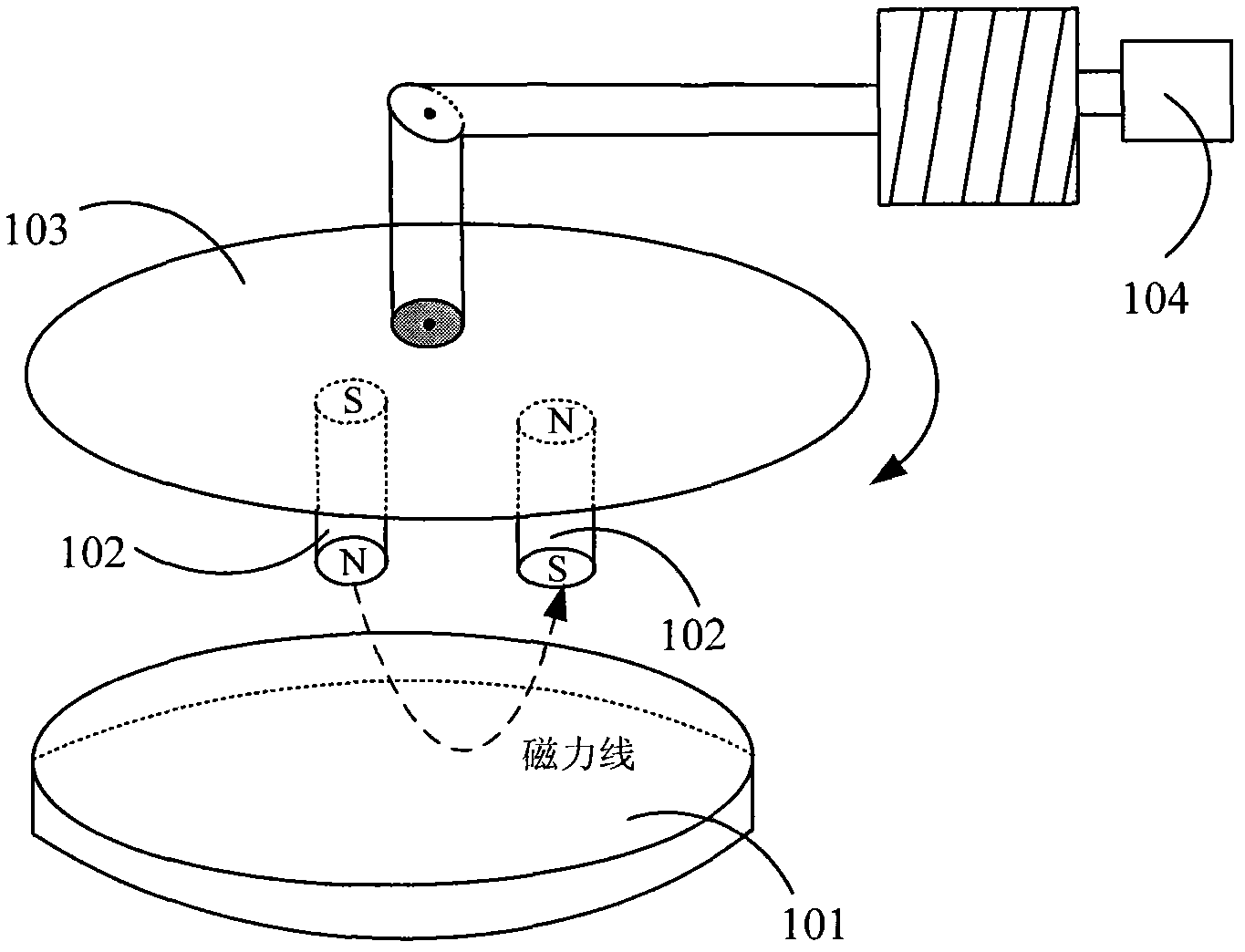
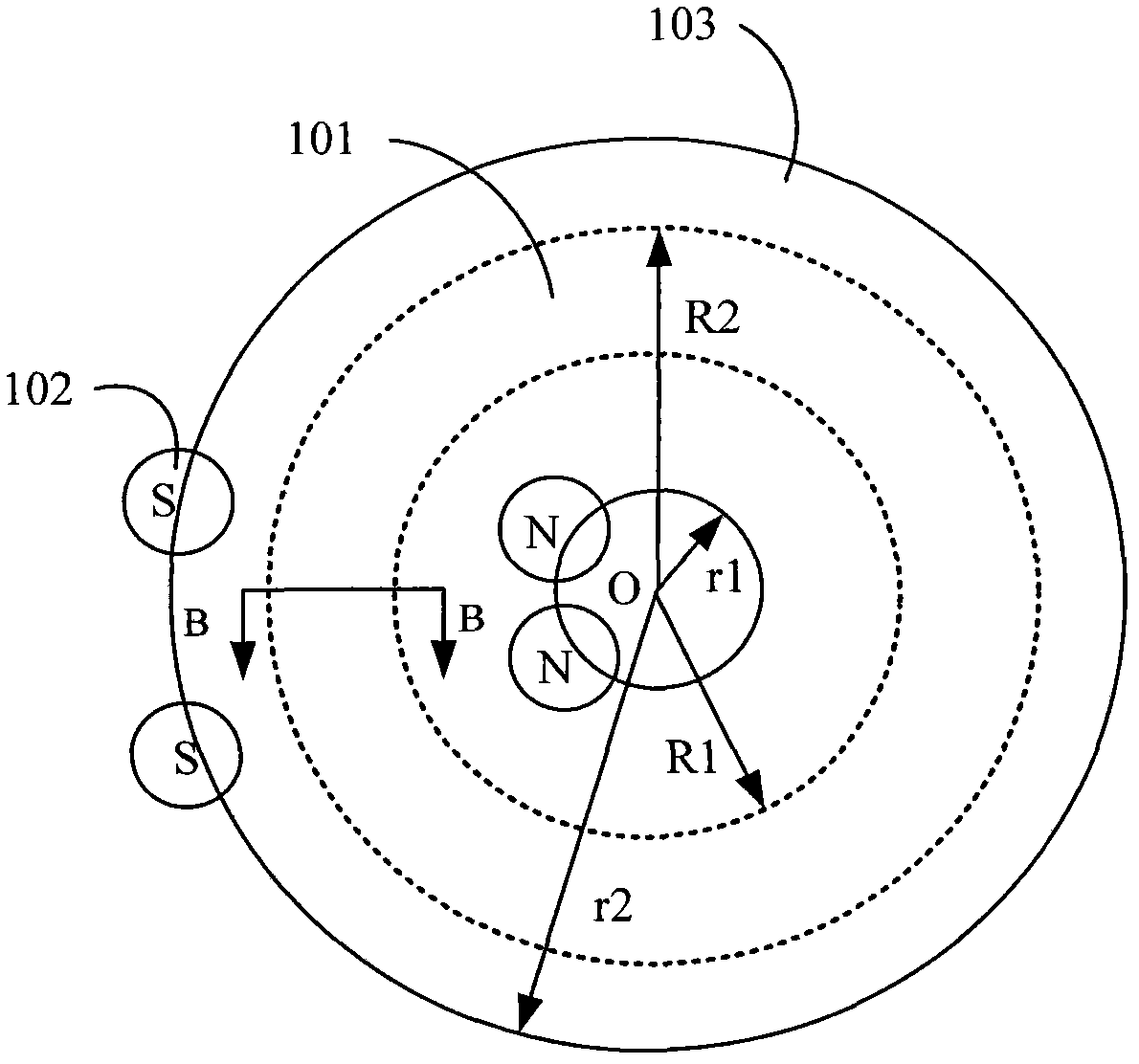
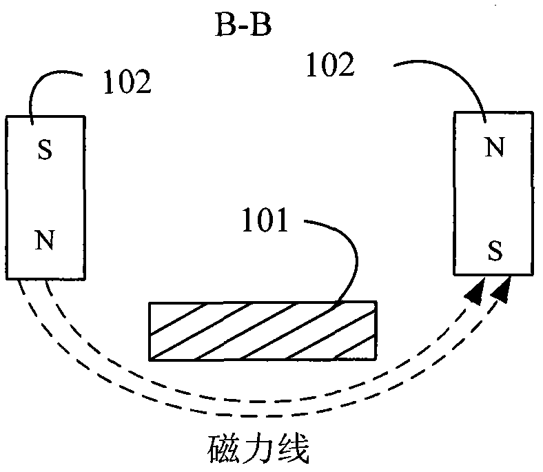
[0032] figure 1 It is a schematic structural diagram of the first specific embodiment of the magnetron sputtering source provided by the present invention. like figure 1 As shown, the magnetron sputtering source according to the embodiment of the present invention includes a target 101, a magnet, a fixing plate 103 and a power source 104; wherein, the magnet is fixedly arranged on the fixing plate 103, and the magnet may include a plurality of magnets 102, and a plurality of magnets 102 Non-uniformly distributed on the fixed plate 103; the target material 101 and the fixed plate 103 are arranged parallel to the central axis, and the target material 101 and the fixed plate 103 can both rotate around their respective central axes. The sputtering surface of the target material 101 and the fixed plate The planes...


PUM


Abstract

The invention relates to a magnetron sputtering source and magnetron sputtering device. The magnetron sputtering source comprises a target, a magnet, a fixed plate and a power supply, wherein, the magnet is arranged on the fixed plate, the fixed plate is connected with the power supply, the power supply is used for driving the fixed plate to rotate around its central shaft, the target is arranged parallel to the central shaft of the fixed plate, and the target moves relative to the fixed plate. According to the invention, by the relative motion of the target and the fixed plate which is provide with the magnet, the magnetic field generated by the magnet can scan every position of the target to adjust the movement track of secondary electrons and increase the collision frequency of the secondary electrons and argon atoms, and then the argon atoms can be fully ionized to generate more argon ions, thus the sputtering utilization rate and sputtering uniformity of the target in the process that the argon ions bombard the target.

Description

technical field [0001] The invention relates to magnetron sputtering technology, in particular to a magnetron sputtering source and magnetron sputtering equipment. Background technique [0002] In the semiconductor industry integrated circuit manufacturing industry, magnetron sputtering technology is mostly used, which is mainly used for the deposition of metal films such as aluminum and copper to form metal contacts, metal interconnect lines, and the like. [0003] In the process, the magnetron sputtering process can be as follows: the electrons in the process chamber move to the substrate under the action of the electric field, and collide with the argon atoms in the process of flying to the substrate, so that the argon atoms are ionized to obtain positively charged argon ions. and secondary electrons; among them, the argon ions gain momentum in the process of accelerating toward the target with negative potential, and bombard the target to sputter the target to generate s...

Claims


Application Information

Patent Timeline
IPC IPC(8): C23C14/35
Inventor 杨柏
Owner BEIJING NAURA MICROELECTRONICS EQUIP CO LTD
Why Eureka
Try Eureka