Special powder metallurgy gear wheel and preparation method thereof
A powder metallurgy and gear plate technology, applied in belts/chains/gears, mechanical equipment, components with teeth, etc., can solve the problems of cracking in the finale area and other properties of the product that do not meet the requirements for use, and achieve low production costs. , suitable for automated production, the effect of high product strength
- Summary
- Abstract
- Description
- Claims
- Application Information
AI Technical Summary
Problems solved by technology
Method used
Image

Examples
Embodiment 1
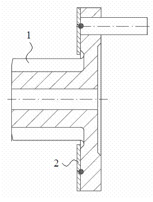
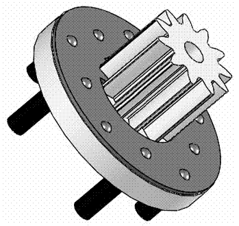
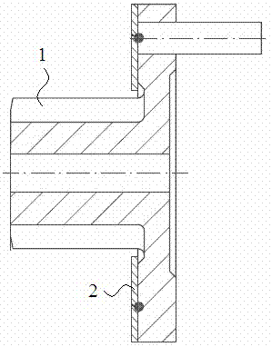
[0017] Such as figure 1 As shown, the special powder metallurgy gear disc is composed of a gear disc 1 and a gasket 2, and the contact end surface between the gear disc 1 and the gasket 2 is connected by welding. During the preparation, operations such as forming, sintering, carburizing, and pressing are performed on the ordinary gear disc, and then the gasket is pressed on the gear disc, and the contact surface is welded into a whole through resistance. The specific preparation method is as follows:
[0018] (1) The gear disc is prepared according to the following powder metallurgy raw materials in parts by weight: Fe: 92.0 parts, C: 0.8 parts, Ni: 4.5 parts, Mo: 1.2 parts, Cu: 1.5 parts;
[0019] (2) Forming (60-ton forming machine), sintering (1120°C×0.5h), carburizing (830°C×2h, Cp: 0.8) and finalization (ordinary 1-ton press) were performed in sequence to produce gear plate.
[0020] (3) Press the gasket on the gear plate, and weld the shaft end face and the gear plate...
Embodiment 2
[0023] The preparation method is the same as in Example 1, wherein the gear disc is prepared according to the following powder metallurgy raw materials in parts by weight: Fe: 95.4 parts, C: 0.6 parts, Ni: 2.5 parts, Cu: 1.5 parts;
[0024] Required specification value Product actual value product density 7.0g / cm 3 MIN 7.15g / cm 3 Shaft breakout force 150kgf MIN 165~190kgf Product torque 1000kgf MIN 1250~1500kgf Tooth resistance 800kgf MIN 1200kgf Gear precision JIS6 grade JIS5 grade
Embodiment 3
[0026] The preparation method is the same as in Example 1, wherein the gear disc is prepared according to the following powder metallurgy raw materials in parts by weight: Fe: 91.0 parts, C: 0.5 parts, Ni: 3.0 parts, Mo: 0.5 parts, Cu: 3.0 parts.
[0027] Required specification value Product actual value product density 7.0g / cm 3 MIN 7.15g / cm 3 Shaft breakout force 150kgf MIN 165~190kgf Product torque 1000kgf MIN 1250~1500kgf Tooth resistance 800kgf MIN 1200kgf Gear precision JIS6 grade JIS5 grade
[0028] The manufacturing method of the special powder metallurgy gear plate of the present invention is easy to produce and operate, suitable for automatic production, high in production efficiency, can produce 4000PCS products every 8 hours, and has low production cost and high product strength, has good economic prospects, and can produce produce good social benefits.
PUM
 Abstract
Description
Claims
Application Information
 - R&D
- Intellectual Property
- Life Sciences
- Materials
- Tech Scout
- Unparalleled Data Quality
- Higher Quality Content
- 60% Fewer Hallucinations
Browse by: Latest US Patents, China's latest patents, Technical Efficacy Thesaurus, Application Domain, Technology Topic, Popular Technical Reports.
© 2025 PatSnap. All rights reserved.Legal|Privacy policy|Modern Slavery Act Transparency Statement|Sitemap|About US| Contact US: help@patsnap.com