Device and method for buffering data in dynamic reconfigurable array

A data cache and array technology, applied in data transformation, electrical digital data processing, general-purpose stored program computer, etc., can solve the problem of slow external memory read and write speed, the algorithm structure cannot be arranged into the array, and affects the calculation of dynamic reconfigurable processors. performance and other issues, to achieve the effect of reducing the number of data transfers, reducing the number of configurations, and achieving array expansion.

Active Publication Date: 2013-07-17
TSINGHUA UNIV
View PDF3 Cites 0 Cited by
  • Summary
  • Abstract
  • Description
  • Claims
  • Application Information

AI Technical Summary

Problems solved by technology

[0004] Due to the limitation of the scale of the reconfigurable array, it is very easy for part of the structure of the algorithm to be placed in the array. At this time, it is required to divide the flow graph of this type of algorithm and increase the number of configurations. The data between configurations is related. The last time The calculation results of the configuration need to be written into the external memory first, and then read from the external memory when the configuration calls the data next time. The read and write speed of the external memory is relatively slow, which affects the computing performance of the dynamically reconfigurable processor.

Method used


Image

  • Device and method for buffering data in dynamic reconfigurable array
  • Device and method for buffering data in dynamic reconfigurable array
  • Device and method for buffering data in dynamic reconfigurable array

Examples


Embodiment 1

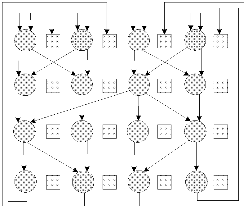
[0087] The circles in the data flow diagram represent processing units, and the squares represent register file subunits.

[0088] refer to image 3 and Figure 4 A data flow diagram using Configuration 1 and Configuration 2 of the present application is shown. Configuration 1 and configuration 2 are executed sequentially, and their data are correlated, that is, the four result data output from the data flow graph in configuration 1 after logical operations will be used as the input data of the data flow graph in configuration 2.

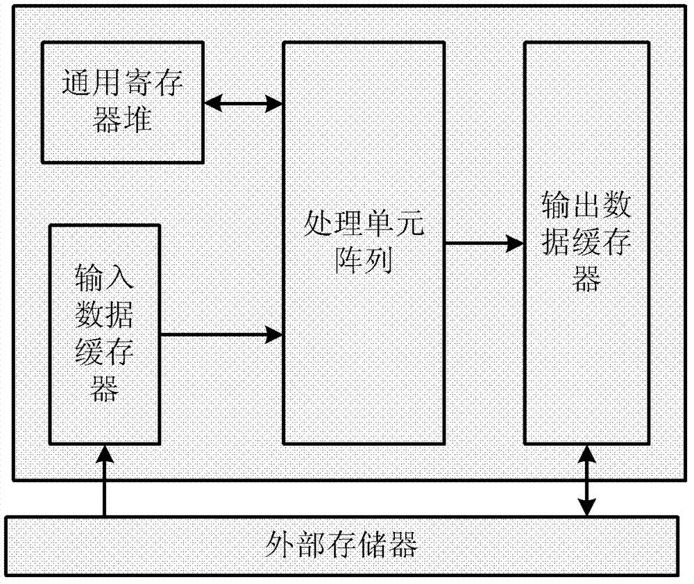
[0089] When the general-purpose register file (Temp_reg) is not introduced, the four result data output in configuration 1 must be input to the output data buffer (Output FIFO) first, and then output to the external memory. When configuration 2 needs to be calculated, the four result data The data is output from the external memory to the input data buffer (Input FIFO), and then input to the processing unit array (RCA) for logical operation.

[0...

Embodiment 2

[0101] refer to Figure 5 and Image 6 The data flow diagram of configuration 3 without using the application and the data flow diagram of configuration 3 after using the application are respectively shown. because Figure 5 The parallel width of the data path in the data flow graph described in the above is 6, which is greater than the width of the processing unit array of 4, so it needs to be decomposed into two sub-graphs and then operated, that is, two operations are required. but if Image 6 After the general-purpose register file is added as shown in , the intermediate data can be cached by the register file, and the additional two paths can be put into it through the general-purpose register file, and the logic operation operation can be completed synchronously with the other four paths.

[0102] Therefore, through the general-purpose register file, additional data paths of the dynamic reconfigurable array can be added to realize array expansion, making the configura...

Embodiment 3

[0119] refer to Figure 7 and Figure 8 The data flow diagram of configuration 4 without using the application and the data flow diagram of configuration 4 after using the application are respectively shown.

[0120] The process of data processing for configuration 4 without using this application includes:

[0121] S41, the external memory outputs the data IN0-IN8 to the input data buffer;

[0122] S42, the input data buffer outputs the data IN0-IN7 to the first row of the processing unit array for calculation; the calculation result of the first row is passed to the second row; so continue to the third row to transfer the result data to the fourth row;

[0123] S43, the input data buffer outputs the data IN8 to the fourth row of the processing unit array, and the fourth row performs a logical operation on the result data input from the third row and IN8 to obtain the result data OUT0-OUT1;

[0124] S44, output the operation result data OUT0-OUT1 to the output data buffer;...


PUM


Abstract

The invention provides a device and a method for buffering data in a dynamic reconfigurable array, wherein the device concretely comprises an input data buffer, a processing unit array, a general purpose register file and an output data buffer, wherein the input data buffer is used for reading in data from an external storage, buffering the data, and outputting the data to the processing unit array when needed; the processing unit array is used for reading in data from the input data buffer or the general purpose register file, and carrying out logical operation on the data; the general purpose register file is used for being interconnected with the processing unit array, reading in data from the processing unit array, buffering the data, and outputting the data to the processing unit array when needed; and the output data buffer is used for buffering result data processed by the processing unit array and reading out the data to the external storage when needed. According to the invention, the times for reading and writing the data between the dynamic reconfigurable array and the external storage can be reduced, and thus the performance of a dynamic reconfigurable processor is improved.

Description

technical field [0001] The present application relates to the technical field of embedded systems, in particular to a device and method for caching data in a dynamically reconfigurable array. Background technique [0002] Dynamic reconfigurable processor is a new type of processor architecture, which combines the flexibility of software and the efficiency of hardware. Compared with traditional single-core microprocessors, it can not only change the control flow, but also change the data path. It has the advantages of high performance, low power consumption, good flexibility, and good scalability, and is especially suitable for processing computationally intensive algorithms, such as media processing, pattern recognition, and baseband processing. Therefore, dynamically reconfigurable processors have also become an important development direction of the current processor structure, such as the ADRES processor of the European Microelectronics Center (IMEC) and the CHESS process...

Claims


Application Information

Patent Timeline
Patent Type & Authority Patents(China)
IPC IPC(8): G06F5/06G06F15/78
Inventor 刘雷波朱敏王延升朱建峰杨军曹鹏时龙兴尹首一魏少军
Owner TSINGHUA UNIV
Why Eureka
Try Eureka