Multi-link aggregated data transmitting method and system

A data transmission method and multi-link aggregation technology, applied in the direction of digital transmission system, transmission system, data exchange network, etc., can solve the problems such as the inability to expand the business, prolong the standby time, the business is not universal, etc., to solve the problem of data transmission The effect of limited bandwidth, good generality

Inactive Publication Date: 2012-04-04
廖小明
View PDF5 Cites 30 Cited by
  • Summary
  • Abstract
  • Description
  • Claims
  • Application Information

AI Technical Summary

Problems solved by technology

It can be seen that although my country's 3G access network has been widely deployed, the penetration rate of 3G users is still very low. Therefore, there is still a lot of room for development of 3G applications to some extent.
[0004] 3G network requires good quality of service, backward compatibility and compatibility with fixed network, and high-speed multimedia service capabilities, etc., but the existing 3G technology still has a gap with this goal. 3G terminals support and extend multimedia services. Standby time, unified application platform, etc. need to be further improved. Due to network quality, terminal bottlenecks, and lack of suitable business models, the development of high-speed multimedia services that reflect 3G differentiated services is not ideal.
[0008] Although this transmission method uses multiple transmission links to expand the bandwidth of data transmission, this transmission model itself has a great defect: since the multi-mode terminal as the service receiver has multiple IP addresses, therefore, for For a business application type with only one destination port and one source port, its business data cannot be directly transmitted through multiple IP links, that is, figure 2 The transmission method shown cannot realize data transmission for some services
It can be seen that the existing multi-link transmission mode is not universal for services, and the services cannot be well expanded in the original terminals of the network.

Method used


Image

  • Multi-link aggregated data transmitting method and system
  • Multi-link aggregated data transmitting method and system
  • Multi-link aggregated data transmitting method and system

Examples


Embodiment 1

[0048] like Figure 5 Shown is a first embodiment of a multi-link aggregation data transmission method and system of the present invention, which is applied to a mobile video conferencing system for video data transmission.

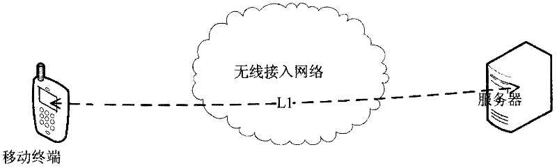
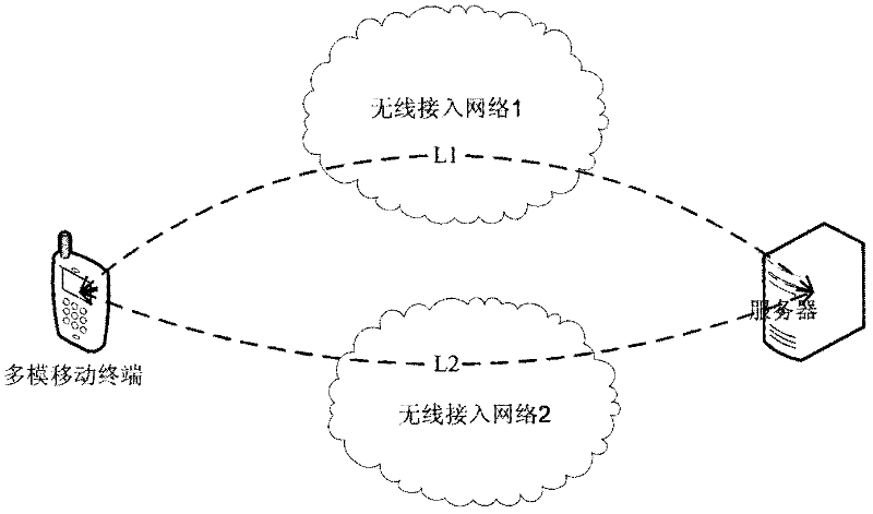
[0049] The multi-link aggregation data transmission system includes a mobile terminal A of the video conferencing system as the sending end device and a command center B of the video conferencing system as the receiving end device, and also includes a 3G router connected to the mobile terminal A and a command center connected to the command center. The access server connected to center B. The mobile terminal A is used to initiate the service application of video data transmission to the command center B. The 3G router has two 3G network cards, correspondingly supporting two 3G links L1 and L2. The access server is connected to a small local area network, and the command center B in the small local area network is a data receiving end.

[0050] Specific...

Embodiment 2

[0060] like Image 6 As shown, in the data transmission method of the present invention, the command center B connected to the access server can also serve as a data sender to send data to the mobile terminal A connected to the 3G router.

[0061] Wherein, the data sending end is the command center B in the local area network, and the local area network is connected to the public network through the access server, and the data receiving end is the mobile terminal A of the video conferencing system. Same as Embodiment 1, the 3G router connected to mobile terminal A has two 3G network cards, and supports two 3G links L1 and L2 accordingly.

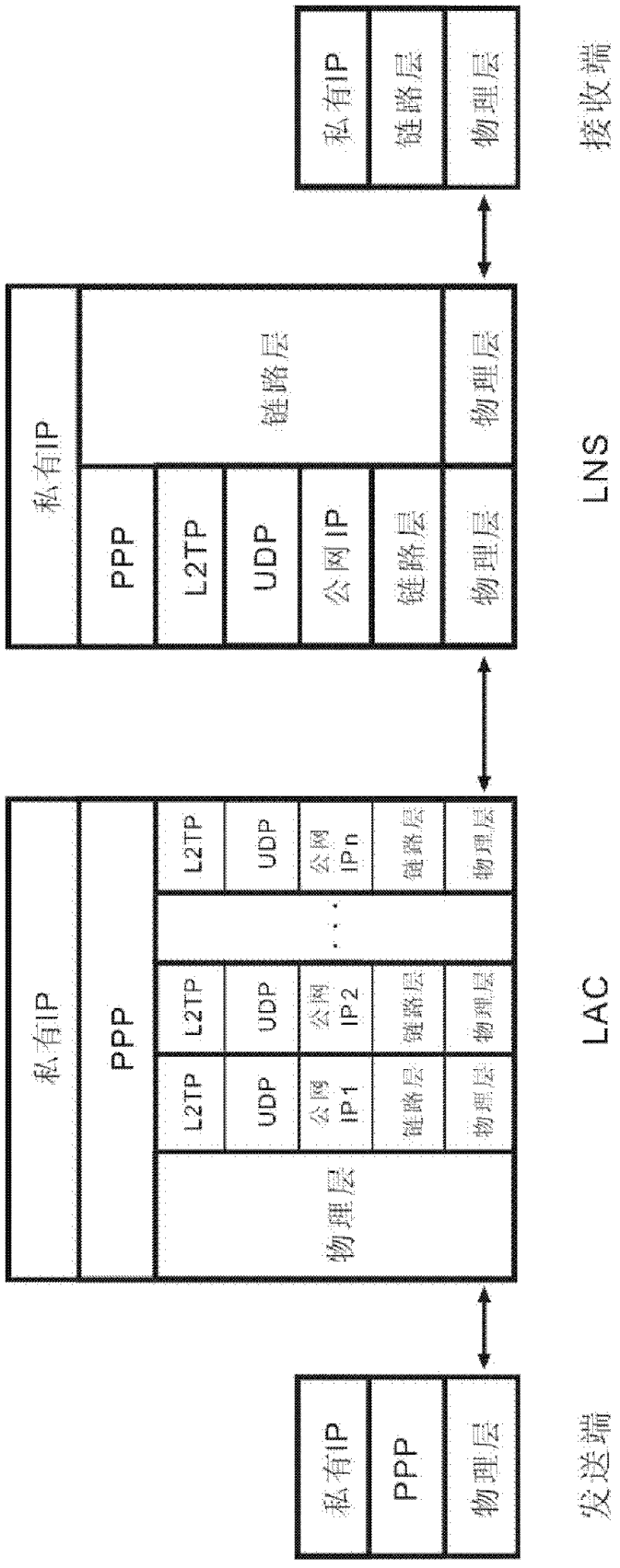
[0062] Image 6In the second embodiment of the present invention shown, the specific method for the command center B to transmit data to the mobile terminal A is similar to the transmission method in Embodiment 1, the difference is: 1) the access server receives the data from the command center B The IP message is encapsulated into a PPP f...

Embodiment 3

[0064] The data transmission method of the present invention can also be applied to data transmission between any mobile terminals in a video conference system. like Figure 7 As shown, it is a schematic flow diagram of mobile terminal A sending data to another mobile terminal C as a data sending end. Wherein, the 3G router connected to mobile terminal C is the same in structure and function as the 3G router connected to mobile terminal A, and the IP address of mobile terminal C is IP-SC.

[0065] The process of transmitting the IP message of the video data from the mobile terminal A to the access server side is the same as that in Embodiment 1. The access server decapsulates the received PPP frame and restores it to the original video data sent by the mobile terminal A. IP message, the destination address carried in the IP message after decapsulation is obtained as IP-SC, and the data receiving end is determined to be the mobile terminal C, so the IP message is transmitted t...


PUM


Abstract

The invention discloses a multi-link aggregated data transmitting method and a system, which is applied to systems comprising L2TP VPN of LAC and LNS. The method comprises the following steps: building a plurality of L2TP tunnels on a plurality of links between the LAC and the LNS; receiving the IP message coming from a piece of transmitting terminal equipment by the LAC, and executing the PPP encapsulation; transmitting the PPP frames to the LNS through the multiple L2TP tunnels built on the VPN; decapsulating the received PPP frames by the LNS as the original IP message transmitted by the transmitting terminal equipment, and transmitting to a piece of receiver terminal equipment. The multiple links can be aggregated as one logic link based on un-changing the source address and the destination address of the service and un-changing the original port, so seamless connection with the current internet can be realized. The method and system can be applied to communications of various service application types and have good university.

Description

technical field [0001] The invention belongs to the communication field, and in particular relates to a data transmission method and system for multi-link aggregation on a public communication channel in a wireless and mobile environment. Background technique [0002] At present, the second-generation mobile communication technology, that is, the Global System for Mobile Communications (GSM) network has matured, and ordinary voice services are basically saturated. With the development of social science and technology, the innovation of communication technology is also changing with each passing day. The emergence of cellular mobile communication technology that supports high-speed data transmission, that is, the third generation mobile communication technology (3G), has brought the development of mobile communication into a new era of data services. . 3G technology makes mobile communication and the Internet more closely integrated, and it is getting closer to people's live...

Claims


Application Information

Patent Timeline
Patent Type & Authority Applications(China)
IPC IPC(8): H04L12/56H04L47/41
Inventor 廖小明
Owner 廖小明
Why Eureka
Try Eureka