
Intelligent robot system and charging butting method thereof

一种智能机器人、充电座的技术,应用在智能机器人领域,能够解决清扫机掉电、充电失败等问题,达到可靠充电、防止掉电、避免分离的效果

Active Publication Date: 2012-04-11
ECOVACS ROBOTICS (SUZHOU ) CO LTD
View PDF7 Cites 22 Cited by
  • Summary
  • Abstract
  • Description
  • Claims
  • Application Information

AI Technical Summary

Problems solved by technology

Therefore, on this basis, there are the following problems according to the current charging and docking method: since the current charging and docking method is that once it detects that there is a voltage or current on the docking electrode of the cleaning machine, it is considered that the docking is successful. The first motor drives the traveling wheels, and at this time, since the traveling wheels are in a free state, it is very likely that the first motor will continue to move forward or backward after releasing the control of the traveling wheels by the first motor, so that the contact between the butt electrode of the cleaning machine and the charging stand The charging electrodes are separated, causing the cleaning machine to lose power and fail to charge during charging

Method used


Image

  • Intelligent robot system and charging butting method thereof
  • Intelligent robot system and charging butting method thereof
  • Intelligent robot system and charging butting method thereof

Examples


Embodiment 1

[0041] In a specific embodiment of the present invention, the actuating mechanism 107 for locking the electrodes is a first electric motor with a braking coil. Figure 7 It is a block diagram of the working principle of the control walking unit in Embodiment 1 of the present invention, as Figure 7 As shown, the control running unit 1053 includes: a triode drive circuit 1053a and a triode control circuit 1053b. Figure 5 It is a schematic diagram of the triode control circuit in the control walking unit of an embodiment of the present invention, Image 6 It is a schematic diagram of the relationship between the input and output signals of the triode drive circuit in this embodiment of the present invention. combine Figure 5 with Figure 7 It can be seen that the transistor control circuit 1053b includes a transistor Q1 and a relay K1; wherein the relay K1 includes a relay coil K11 and a relay contact switch K12. The output signal of the transistor driving circuit 1053a is...

Embodiment 2

[0044] Figure 8A-Figure 8D It is a structural schematic diagram of the braking device of Embodiment 2 of the present invention, Figure 9 It is a working principle block diagram of Embodiment 2 of the present invention. Such as Figure 8A with Figure 9 As shown, the control walking unit 1053 includes: a second motor 1053d, its driving circuit 1053c and a transmission mechanism 1053e, the second motor 1053d is based on the first motor of the intelligent robot 100 itself, in order to control A new motor is added to the device. The pull rod 1702 is connected to the second motor 1053d through a transmission mechanism 1053e that converts the motor's rotational motion into a linear motion by using gears, racks, etc., and is controlled by the second motor 1053d. 'Through the perforation of the pull rod 1702, it is connected and fixed with the swing rod 1703; one end of the swing rod 1703 is provided with a perforation, and the swing rod rotation shaft 1703' is connected and fix...


PUM


Abstract

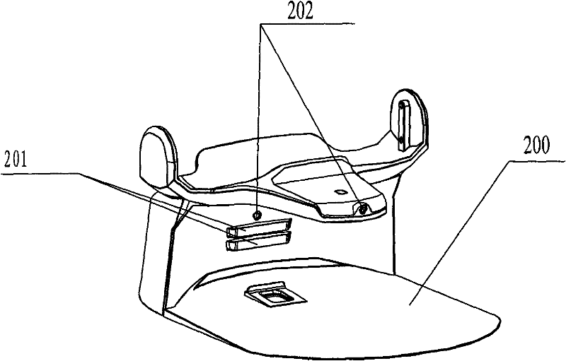
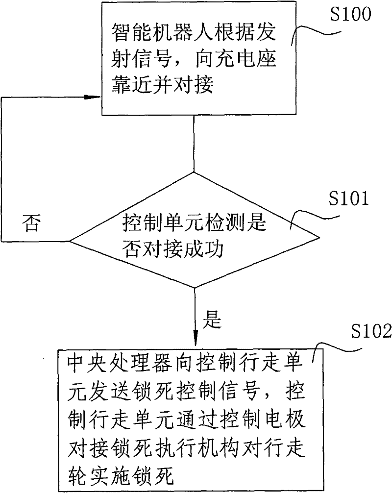
The invention relates to an intelligent robot system. The system comprises an intelligent robot and a charging seat, wherein the intelligent robot comprises a butting electrode, a traveling mechanism, a control unit and an electrode butting locking execution mechanism; the butting electrode, the traveling mechanism and the control unit are arranged on a body of the intelligent robot; the charging seat comprises a charging electrode; and the charging electrode is arranged on a body of the charging seat. When the butting electrode is successfully butted with the charging electrode, the control unit controls the electrode butting locking execution mechanism to act to lock the traveling mechanism, and the intelligent robot is successfully butted with the charging seat, so that the phenomenon that the butting electrode is separated from the charging electrode of the charging seat because the traveling mechanism moves inappropriately is avoided, the conditions of power failure and charging failure when the intelligent robot is charged are effectively avoided, and the intelligent robot can be stably and reliably charged.

Description

technical field [0001] The invention relates to the field of intelligent robots, in particular to an intelligent robot system and a charging and docking method thereof. Background technique [0002] With the advancement of the times and the rapid development of science and technology, smart devices, such as robots, have become well-known products. Not only that, smart sweepers, smart mopping machines and other similar ground cleaning robots, with their convenient cleaning, time-saving and labor-saving features, enable people to get rid of tedious housework and enter the family life of ordinary people. [0003] The ground cleaning robots currently on the market, such as intelligent sweepers, have built-in rechargeable batteries, cleaning units and dust boxes. The charging stand used with the sweeper provides power to the rechargeable battery. The cleaning machine includes a cleaning mode and a charging mode. In the cleaning mode, the energy is supplied by a rechargeable bat...

Claims


Application Information

Patent Timeline
Patent Type & Authority Applications(China)
IPC IPC(8): B25J9/00B25J13/00B25J19/00H02J7/00
CPCH02J7/0044B25J19/005A47L2201/022H02J7/0042
Inventor 汤进举
Owner ECOVACS ROBOTICS (SUZHOU ) CO LTD
Learn More