Automatic flushing device for urban drainage pipeline system

A technology for drainage pipes and automatic flushing, which is applied in waterway systems, water supply devices, cleaning sewer pipes, etc., and can solve problems such as high cost and complex structure

Active Publication Date: 2012-04-11
管丽环境技术(上海)有限公司
View PDF4 Cites 10 Cited by
  • Summary
  • Abstract
  • Description
  • Claims
  • Application Information

AI Technical Summary

Problems solved by technology

Existing pipe cleaning devices are generally scraping tools for pipe wall dirt or cleaning equ...

Method used


Image

  • Automatic flushing device for urban drainage pipeline system
  • Automatic flushing device for urban drainage pipeline system
  • Automatic flushing device for urban drainage pipeline system

Examples


Embodiment Construction

[0018] The technical solution of the present invention is described in detail below by specific embodiments in conjunction with the accompanying drawings:

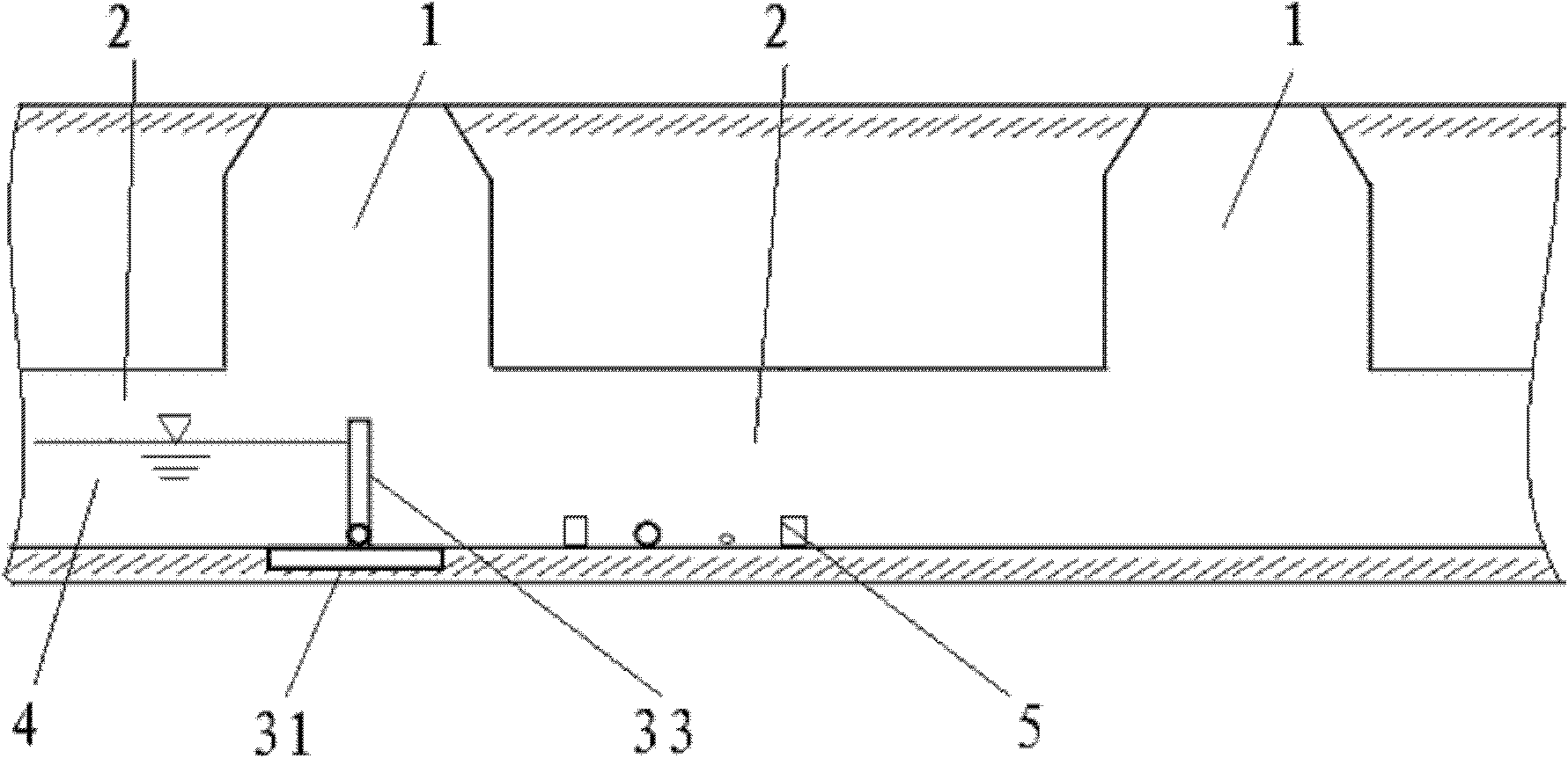
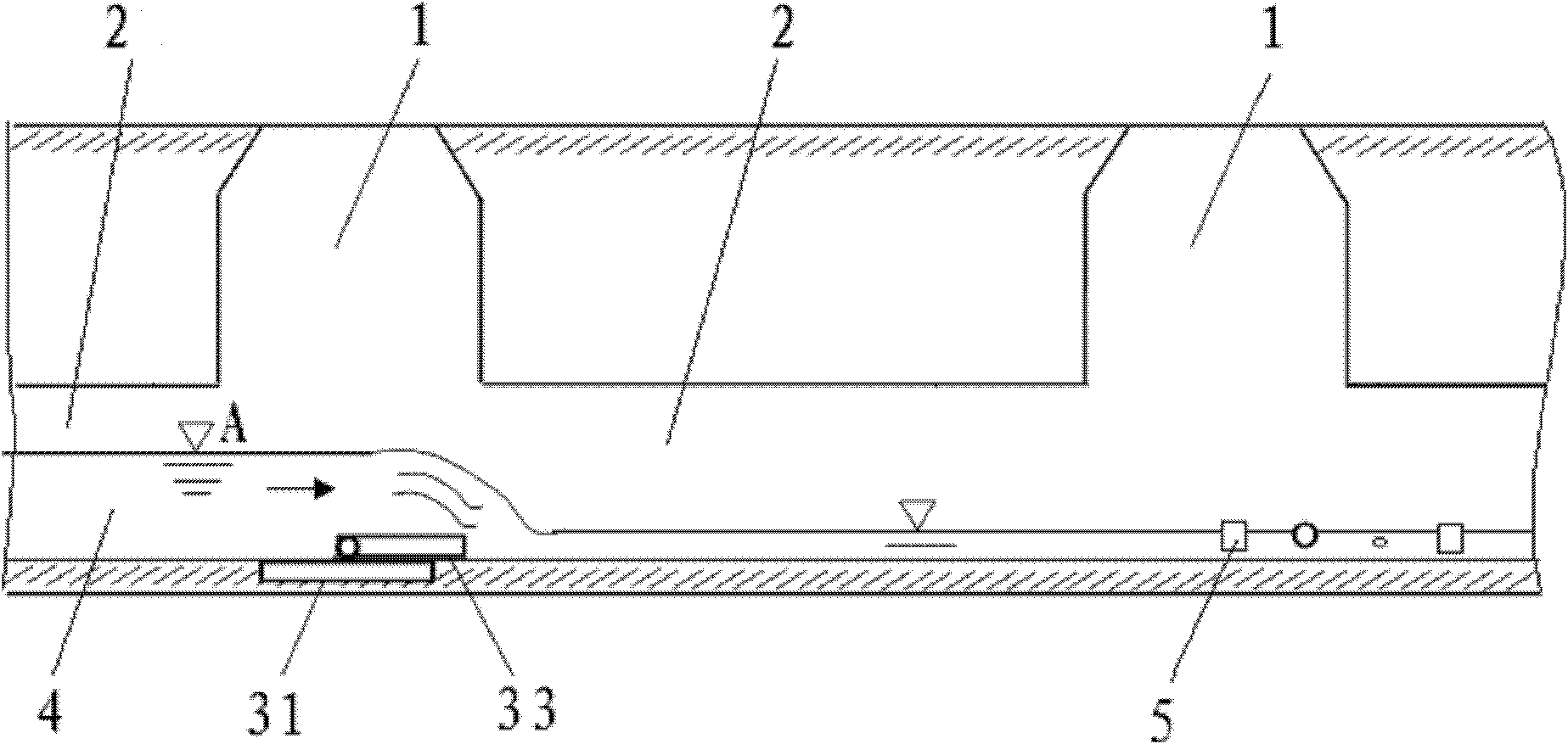
[0019] The urban drainage pipeline system includes an inspection well 1 and a drainage pipeline 2 connected to the lower part of the inspection well 1 . In order to facilitate the maintenance of the pipeline, the width of the inspection well 1 should be greater than the diameter of the drainage pipeline 2 .

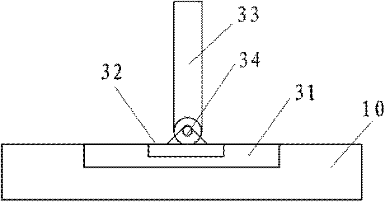
[0020] see figure 1 , an automatic flushing device for urban drainage pipeline system of the present invention, comprising a base 31, a fixed plate 32, a water gate 33 and several spring hinges 34, wherein:

[0021] The base 31 is buried on the bottom surface 10 of the inspection well 1 in such a way that its upper end surface is flush with the bottom surface 10 of the inspection well 1;

[0022] The fixed plate 32 is embedded on the base 31, and the upper end surface of the fixed plate 32 is provided with several h...


PUM


Abstract

The invention discloses an automatic flushing device for an urban drainage pipeline system. The automatic flushing device comprises a base and a water gate, wherein the base is embedded to the bottom of an inspection well in a manner that the upper end face of the base is flush with the bottom of the inspection well; the water gate is movably connected to the upper end face of the base in a manner of blocking the water flow of an upstream drainage pipeline; when the water level in the upstream drainage pipeline of the water gate reaches an effective height, the water gate can be pushed down towards the downstream side and laid flat, and the accumulated water is discharged downstream; and when the water level in the upstream drainage pipeline of the water gate is lowered to another effective height, the water gate is automatically raised, and the state of closing the upstream drainage pipeline of the water gate is recovered, so that the water can be accumulated in the upstream drainage pipeline of the water gate. The automatic flushing device can be used for flushing pollutants such as sand, solid garbage and the like which are accumulated in the downstream pipeline by using the flushing capacity of the water flow of the high water level when the water flow of the high water level is discharged downstream.

Description

technical field [0001] The invention relates to a supporting facility of a municipal drainage pipeline, in particular to an automatic flushing device for the urban drainage pipeline system. Background technique [0002] In the past, in the design and construction of urban underground drainage pipelines, in order to prevent urban areas from overflowing sewage and flooding and waterlogging due to insufficient pipeline capacity, the diameter of the pipeline was determined according to the instantaneous maximum amount of drainage that the pipeline needs to collect. Choose OK. In this way, when the design instantaneous maximum value of the flow rate does not appear, the water volume inside the pipeline will be relatively small, so that the water flow velocity in the pipeline will not reach the design value, and the sediment and pollutants in the sewage will settle in the pipeline, causing siltation . Especially in combined drainage pipes where rainwater and sewage are discharge...

Claims


Application Information

Patent Timeline
IPC IPC(8): E03F9/00
Inventor 孙跃平孙千惠
Owner 管丽环境技术(上海)有限公司
Why Eureka
Try Eureka