Electromechanical brake and automobile

An electronic mechanical brake and brake caliper technology, applied in mechanical equipment, brake actuators, gear shifting mechanisms, etc., can solve the problems of shortening life, increasing brake volume and cost, and achieving reduced volume and simple structure. , the effect of prolonging the service life

Active Publication Date: 2012-04-11
CHERY AUTOMOBILE CO LTD
View PDF9 Cites 9 Cited by
  • Summary
  • Abstract
  • Description
  • Claims
  • Application Information

AI Technical Summary

Problems solved by technology

However, for the existing electromechanical brakes, since the deceleration mechanism used to increase the torque is arranged at the output end of the motor, how much brake clamping force is needed in the braking process, the motion mechanism will bear the same In this way, in the frequent braking process, the moving mechanism will shorten its life because it often bears a large torque; and the deceleration mechanism set at the output end of the motor is also increased. The size and cost of the brake

Method used


Image

  • Electromechanical brake and automobile
  • Electromechanical brake and automobile
  • Electromechanical brake and automobile

Examples


Embodiment 1

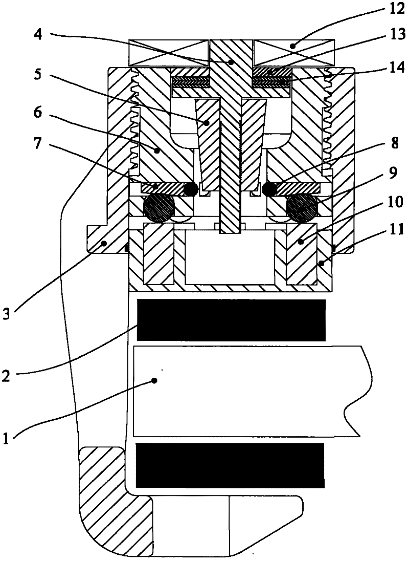
[0028] like figure 1 As shown, in this embodiment, the electromechanical brake includes a brake disc 1 , a friction plate 2 , a brake caliper body 3 , and a power mechanism that can push the friction plate 2 forward to clamp the brake disc 1 .

[0029] Wherein, the power mechanism includes a motor 12, a kinematic mechanism that converts the rotational motion of the motor 12 into a linear motion, a torque booster mechanism that is sleeved on the kinematic mechanism to amplify the torque output by the motor 12, and a torque booster mechanism that is sleeved on the torque booster mechanism and motion The front end of the mechanism and the piston cylinder 11 between the torque booster mechanism and the friction plate 2 .

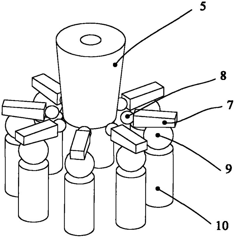
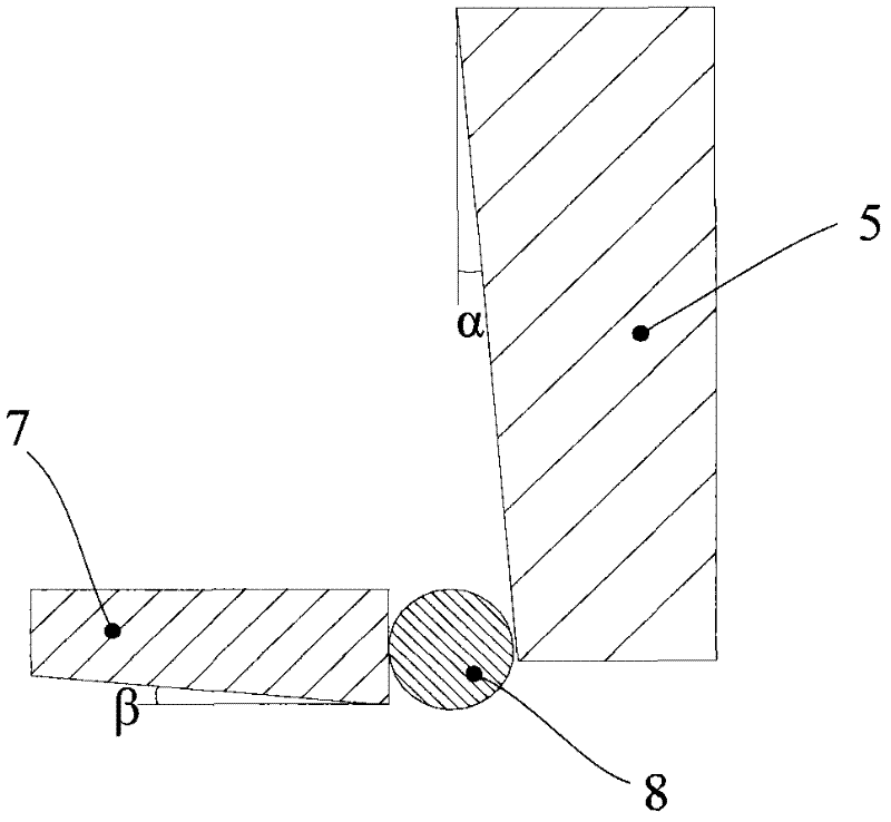
[0030] In this embodiment, the movement mechanism adopts a lead screw mechanism, and the lead screw mechanism includes a lead screw 4 and a first nut 5 sleeved on the lead screw 4. The first nut 5 is an inverted circle with a small front end and a large rear end...

Embodiment 2

[0049] The difference between this embodiment and Embodiment 1 is that the torque multiplier mechanism of this embodiment does not have the first roller 8 .

[0050] Other structures and uses in this embodiment are the same as those in Embodiment 1, and will not be repeated here.

Embodiment 3

[0052] The difference between this embodiment and Embodiment 1 is that this embodiment does not have a piston cylinder 11 , the push rod 10 can directly contact the friction plate 2 , and the push rod 10 is fixedly connected with the corresponding second roller.

[0053] Other structures and uses in this embodiment are the same as those in Embodiment 1, and will not be repeated here.

[0054] The electromechanical brake of the present invention reduces the torque on the lead screw 4 due to the arrangement of a torque increasing mechanism with small volume and simple structure, and also avoids setting a deceleration mechanism at the output end of the motor 12, thereby reducing the volume of the electromechanical brake , Save the cost and prolong the service life of the lead screw 4 .


PUM


Abstract

The invention provides an electromechanical brake which comprises a braking disc (1), a friction plate (2), a braking caliper body (3) and a power mechanism, wherein the power mechanism can push the friction plate (2) to move forwards so as to clamp the braking disc (1); the power mechanism comprises a motor (12) and a moving mechanism which is connected with the output end of the motor (12); the moving mechanism can be used for converting the rotation movement of the motor into linear movement; the moving mechanism is arranged in the braking caliper body (3), wherein the power mechanism also comprises a torque increasing mechanism for amplifying output torque of the motor (12); the input end of the torque increasing mechanism is connected with the output end of the moving mechanism; and the output end of the torque increasing mechanism can come into contact with the friction plate (2). Accordingly, the invention provides an automobile which comprises the brake. The electromechanical brake provided by the invention has the advantages of small volume, simple structure, low cost, long service life and the like compared with the prior art.

Description

technical field [0001] The invention belongs to the technical field of automobile manufacturing, and in particular relates to an electromechanical brake and an automobile including the electromechanical brake. Background technique [0002] With the development of automobile technology, people have put forward higher requirements for automobile power, economy, safety, maneuverability and comfort. The mechanical system in the automobile is gradually converting to the electromechanical system. Electromechanical braking system. [0003] The electromechanical braking system uses electronic components to replace some mechanical components, and replaces all the brake pipelines with wires, which saves a lot of valve components in the braking system, shortens the braking response time, improves the braking performance, and saves In addition, the electronic control unit (ECU) is used to control the braking system as a whole, and each brake has its own control unit. On this basis, var...

Claims


Application Information

Patent Timeline
Patent Type & Authority Applications(China)
IPC IPC(8): F16D65/18F16D121/24
Inventor 高国兴杜金枝王陆林张世兵
Owner CHERY AUTOMOBILE CO LTD
Why Eureka
Try Eureka