Self-excitation retarding device and control method thereof

A retarder, self-excited technology, applied in electromechanical devices, controlling mechanical energy, connecting with control/drive circuits, etc., can solve the problems of difficult installation, high cost, and low output braking torque of the self-excited retarder. The effect of volume and mass reduction, compact structure

Active Publication Date: 2015-07-01
山东大侨发展股份有限公司
View PDF8 Cites 9 Cited by
  • Summary
  • Abstract
  • Description
  • Claims
  • Application Information

AI Technical Summary

Problems solved by technology

[0005] The purpose of the present invention is to solve the problem that the self-excited retarder has a complex structure, large volume and mass, difficult installation, high cost, and the output braking torque of the self-excited retarder is low when the vehicle speed is low

Method used


Image

  • Self-excitation retarding device and control method thereof
  • Self-excitation retarding device and control method thereof
  • Self-excitation retarding device and control method thereof

Examples


Embodiment Construction

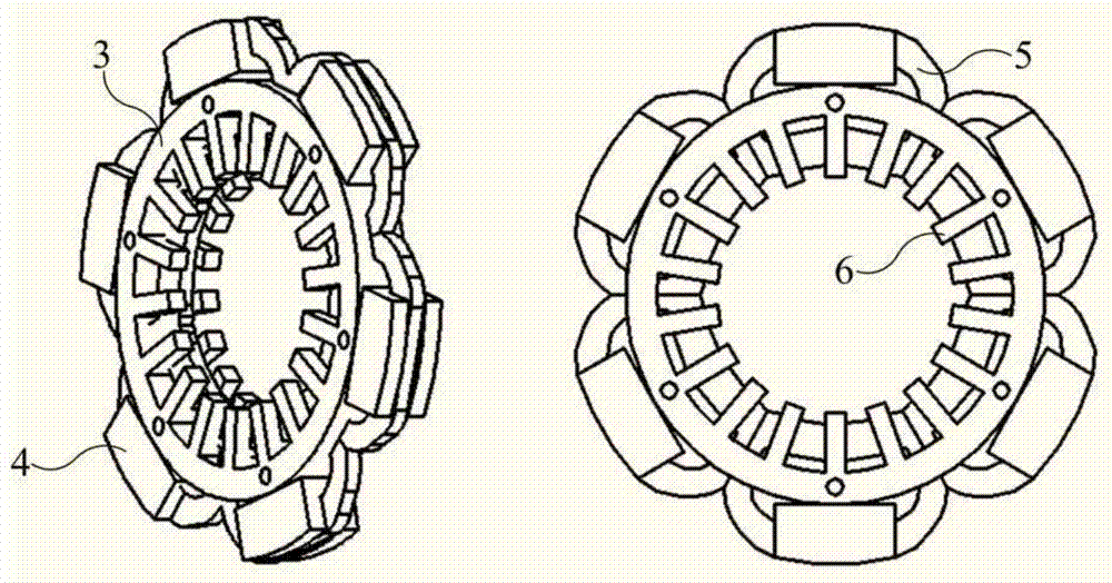
[0031] The structure of the self-excited retarder according to the present invention will be further described below in conjunction with the accompanying drawings. The self-excited retarder includes three parts: stator assembly, rotor assembly and control assembly.

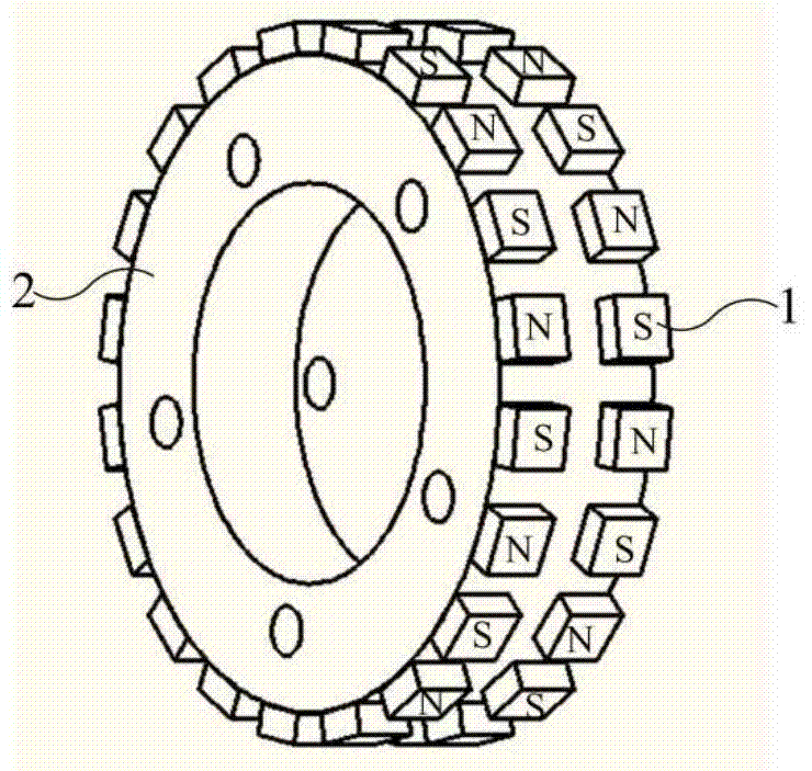
[0032] joint figure 1 , Image 6 and Figure 7 As shown, the self-excited retarder rotor assembly includes an eddy current brake rotor 10 and a generator rotor 11 . The eddy current brake rotor 10 and the generator rotor 11 are coaxially and fixedly connected. Wherein, the rotor 10 of the eddy current brake is connected with the input end of the transmission shaft, and the rotor 11 of the generator is connected with the output end of the transmission. The eddy current brake rotor 10 and the generator rotor 11 rotate synchronously with the automobile drive train.

[0033] like figure 1 As shown, the generator rotor 11 includes a generator rotor bracket 2 and several permanent magnets 1 . Two circles of perma...


PUM


Abstract

The invention relates to a self-excitation retarding device and a control method thereof. The self-excitation retarding device comprises a stator assembly, a rotor assembly and a control assembly, the rotor assembly comprises an eddy current brake rotor and a power generator rotor, the stator assembly comprises a stator support, an eddy current brake stator iron core, a coil winding assembly and a power generator stator iron core, and the control assembly comprises a first solid state relay, a rectifier, a second solid state relay and a third solid state relay. The stators of a retarding and braking portion and a power generating portion are integrated highly, so that the self-excitation retarding device is compact in structure, and both size and mass are reduced to some extent; a power generator stranded wire and an eddy current brake stranded wire are directly connected, so that alternating current output by the power generator stranded wire can be directly fed into the eddy current brake stranded wire, and the self-excitation retarding device can output large braking moment when an automobile travels at a low speed.

Description

technical field [0001] The patent of the invention relates to the field of automobile auxiliary braking, in particular to a self-excited retarder and a control method thereof. Background technique [0002] The eddy current retarder occupies the largest proportion in my country's automobile retarder industry due to its simple structure, low manufacturing cost, short response time, easy intelligent control of braking torque, low failure rate, and convenient maintenance. The use of the eddy current retarder improves the braking stability, driving safety and ride comfort of the car. [0003] However, the negative impact of installing these eddy current retarders on the vehicle is also obvious: 1) The eddy current retarders need to consume a lot of electric energy when they work (the total excitation current is generally above 100A at the highest gear), which brings Additional energy consumption; 2) The huge current required for the operation of the eddy current retarder brings...

Claims


Application Information

Patent Timeline
Patent Type & Authority Applications(China)
IPC IPC(8): H02K49/04H02K7/10H02K1/18H02K11/00H02K11/30
Inventor 衣丰艳何仁周稼铭吕志明刘永辉周长峰张竹林华相纲黄万友
Owner 山东大侨发展股份有限公司
Why Eureka
Try Eureka