
Mask plate defect detection method

A defect detection and mask technology, applied in the field of defect detection, can solve the problems of unsatisfactory detection effect of foggy defects and fine organic pollution, and achieve the effect of reducing manual intervention and good detection rate

Active Publication Date: 2012-04-11
SHANGHAI HUALI MICROELECTRONICS CORP
View PDF4 Cites 17 Cited by
  • Summary
  • Abstract
  • Description
  • Claims
  • Application Information

AI Technical Summary

Problems solved by technology

In this method, the development is to enlarge the attachments for observation, which requires more manual intervention, and the detection effect on foggy defects and fine organic pollution is not satisfactory

Method used

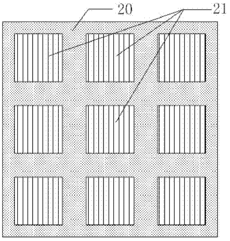
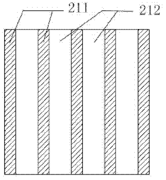

Image

  • Mask plate defect detection method
  • Mask plate defect detection method
  • Mask plate defect detection method

Examples


Embodiment Construction

[0014] The specific embodiment of the present invention will be further described in detail below in conjunction with the accompanying drawings.

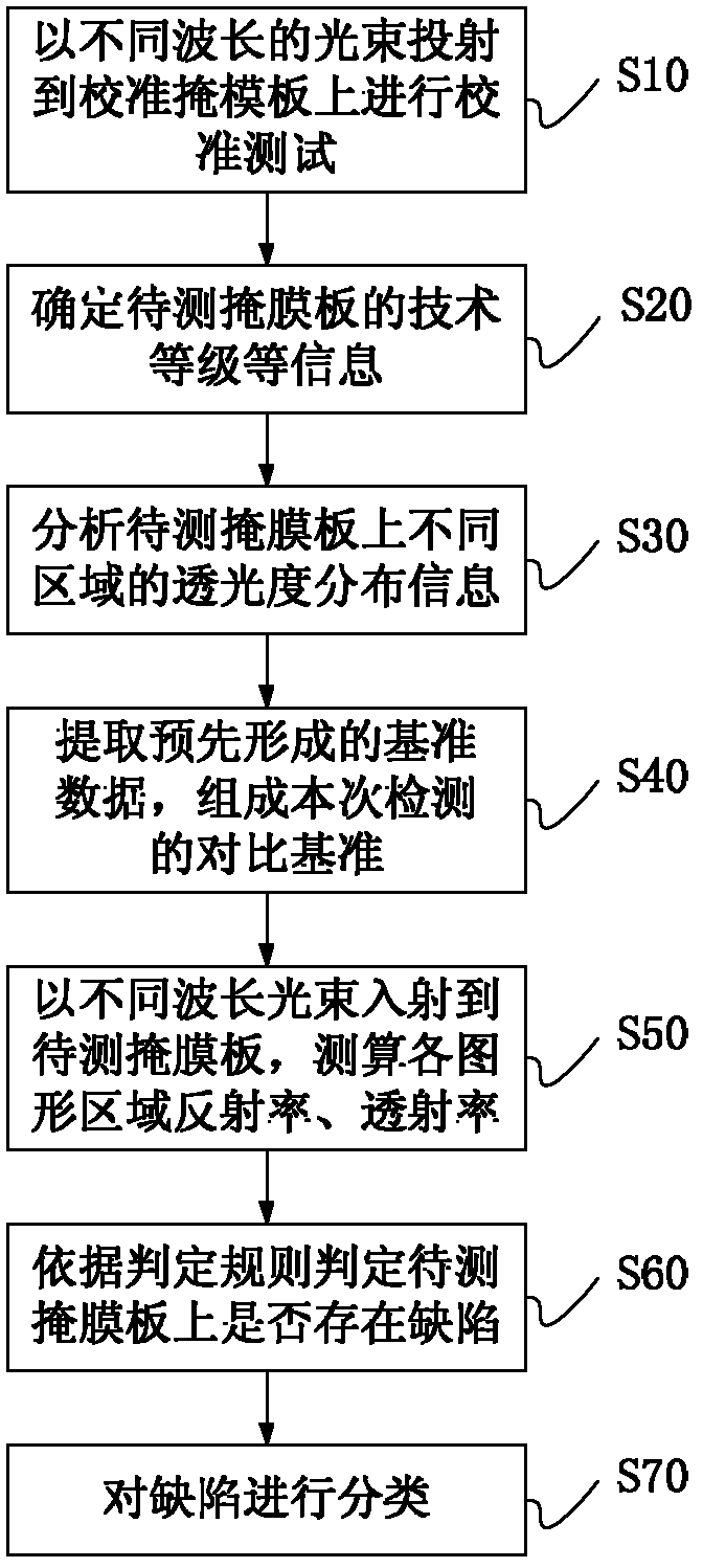
[0015] A mask defect detection method disclosed in the present invention is as follows: figure 1 As shown, it specifically includes the following steps:

[0016] S10: Projecting beams of different wavelengths onto the calibration mask to perform a calibration test;

[0017] S20: Determine the technical level, technical node, and design rules of the mask to be tested;

[0018] S30: analyzing the light transmittance distribution information of different graphic regions of the mask to be tested;

[0019] S40: Extract relevant benchmark data from the benchmark database to form a comparison benchmark for this detection;

[0020] S50: Use beams of different wavelengths to project onto the mask to be tested, and measure and calculate the reflectance and transmittance information of each graphic area;

[0021] S60: Compare the reflectan...


PUM

PropertyMeasurementUnit
wavelengthaaaaaaaaaa

Abstract

The present invention relates to a mask plate defect detection method. The method comprises the following steps that: light beams with different wavelengths are projected onto a calibration mask plate having graphic areas with different transmittance to carry out calibration tests to establish a benchmark database; the light beams are projected onto a mask plate requiring detection, at least one selected from reflectivity or transmissivity of the mask plate requiring detection to the light beams is measured; the information of the measured reflectivity or the measured transmissivity is compared to the benchmark data to determine whether the defect exists on the mask plate requiring detection. With the detection method of the present invention, haze defects and micro organic pollution on the mask plate can be quickly and efficiently detected.

Description

technical field [0001] The present invention relates to a defect detection method, more specifically, to a mask plate defect detection method. Background technique [0002] During the photolithography of silicon wafers using a photomask, ions in the environment tend to form attachments on the mask plate, which affects the exposure beam. When the mask is irradiated by the laser of the lithography machine for a certain period of time, especially under the irradiation of a light source with a wavelength of 193nm or below, so-called haze defects (haze) will gradually be generated on the mask. Ammonium sulfate compound is considered to be the main component of haze defects, and the residual ions after photomask cleaning are considered to be the main cause of haze defects. The presence of haze defects on the mask will cause photolithographic defects, which will lead to a decrease in product yield. Therefore, it is very important to find out the defects of the mask plate in time,...

Claims


Application Information

Patent Timeline
Patent Type & Authority Applications(China)
IPC IPC(8): G03F1/72
Inventor 朱骏张旭昇
Owner SHANGHAI HUALI MICROELECTRONICS CORP
Learn More