
Method for converting PLC program into common Petri net

A technology of program conversion and programming logic, which is applied in the field of mathematical modeling of programmable logic controller programs, and can solve problems such as the increase in scale and structural complexity of industrial control systems, tedious program design and debugging workload, and simple operation.

Active Publication Date: 2012-04-11
HUAQIAO UNIVERSITY
View PDF3 Cites 23 Cited by
  • Summary
  • Abstract
  • Description
  • Claims
  • Application Information

AI Technical Summary

Problems solved by technology

However, the development of PLC programs faces high complexity problems: with the support of fieldbus technology, the scale and structure complexity of industrial control systems grow rapidly, such as subway traffic control systems and nuclear power control systems, etc., and the number of states of the system varies with the number of sensors The number of and executive agencies is increasing exponentially, and the state of the logistics system consisting of only 5 automatic navigation vehicles reaches millions, so the PLC program design faces inherently high computational complexity
[0003] The high computational complexity brings two major engineering problems: (1) The program design and debugging workload is cumbersome and huge, and the program development cycle and development cost are difficult to control; (2) Traditional program debugging cannot verify each state (the number of states is exponential Growth), the correctness and reliability of the program cannot be guaranteed, and program errors may cause serious accidents, such as train collisions, European Ariana 5 rocket explosions, and American Threc-5 radioactive medical accidents, etc.
[0005] The method that has been reported at present is to give the method of converting a single instruction or a simple ladder diagram program into an extended Petri net, which cannot automatically convert a common ladder diagram program, and needs to list a large number of logical relationships when actually simulating and converting a ladder diagram program method, which increases the workload, and the behavior analysis of the extended Petri net is more complicated, which increases the possibility of errors; another method is to use the structural elements of the extended Petri net to describe the basic logic instructions of the PLC ladder diagram, and then Complete the conversion of PLC ladder diagram language
The key to this method is to define transition as a specific event, but from a logical perspective, the operation of the entire network structure is not simpler than the PLC ladder diagram program, and the Petri network structure cannot operate by itself during simulation

Method used


Image

  • Method for converting PLC program into common Petri net
  • Method for converting PLC program into common Petri net
  • Method for converting PLC program into common Petri net

Examples


Embodiment 2

[0080] The present invention is described in detail with the second embodiment "motor forward and reverse circuit".

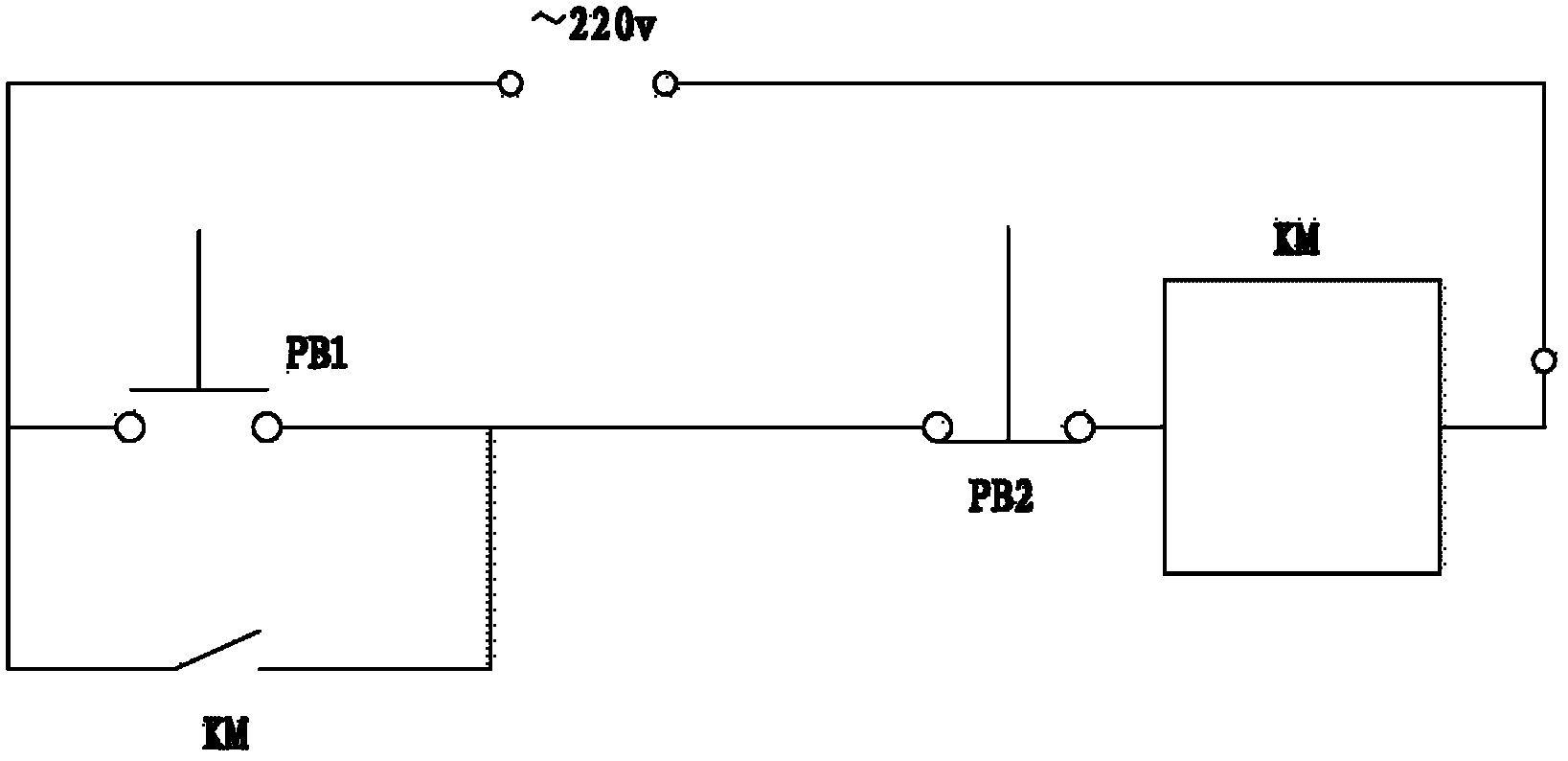
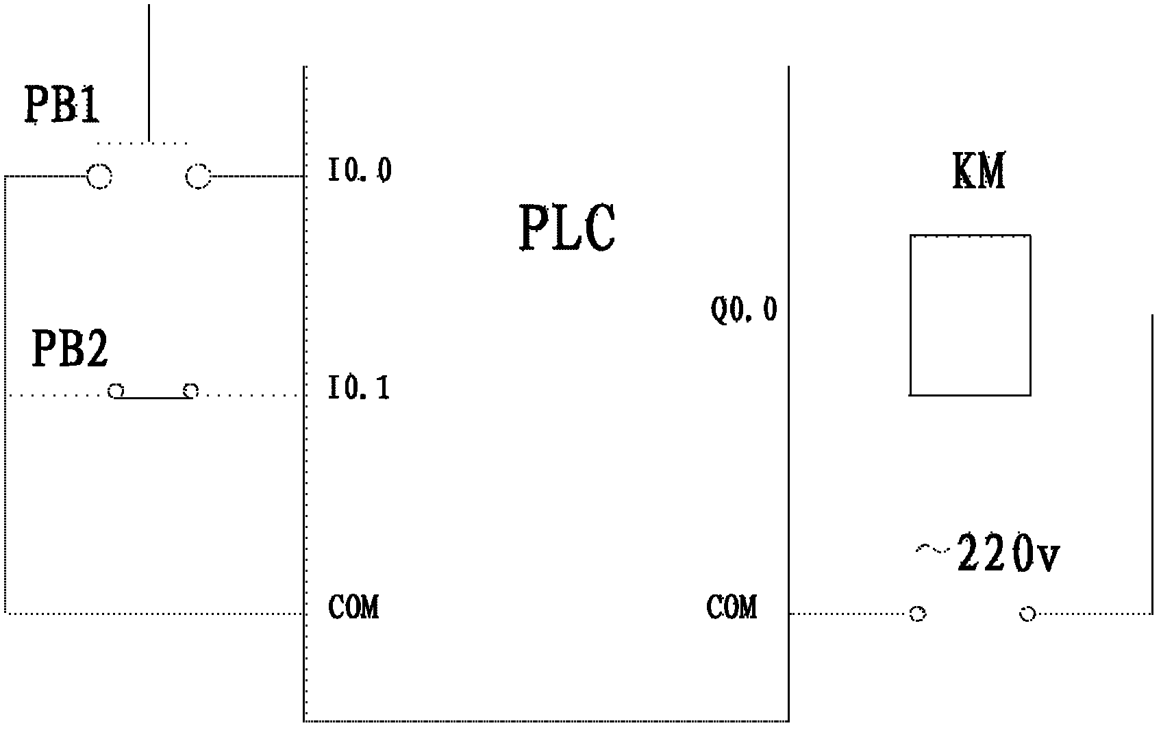
[0081] like Figure 7 As shown, SB1 and SB2 are manual switches, and KM1 and KM2 are relay coils, respectively indicating the forward and reverse working states of the motor. Figure 8 It is the external wiring circuit diagram controlled by PLC. The input terminal I0.0 of one PLC chip is connected to SB1, the output terminal Q0.0 is connected to relay coil KM1, the input terminal I0.1 of the other PLC chip is connected to SB2, and the output terminal Q0.1 is connected to Relay coil KM2. from Figure 9 It can be seen from the PLC ladder diagram program, which illustrates a simple method of interlocking program outputs. When the manual switch SB1 is pressed, the I0.0 contact is closed, the relay KM1 is energized, and the motor rotates forward; when the manual switch SB2 is pressed, the I0.1 contact is closed, the relay KM2 is energized, and the motor rotates f...


PUM


Abstract

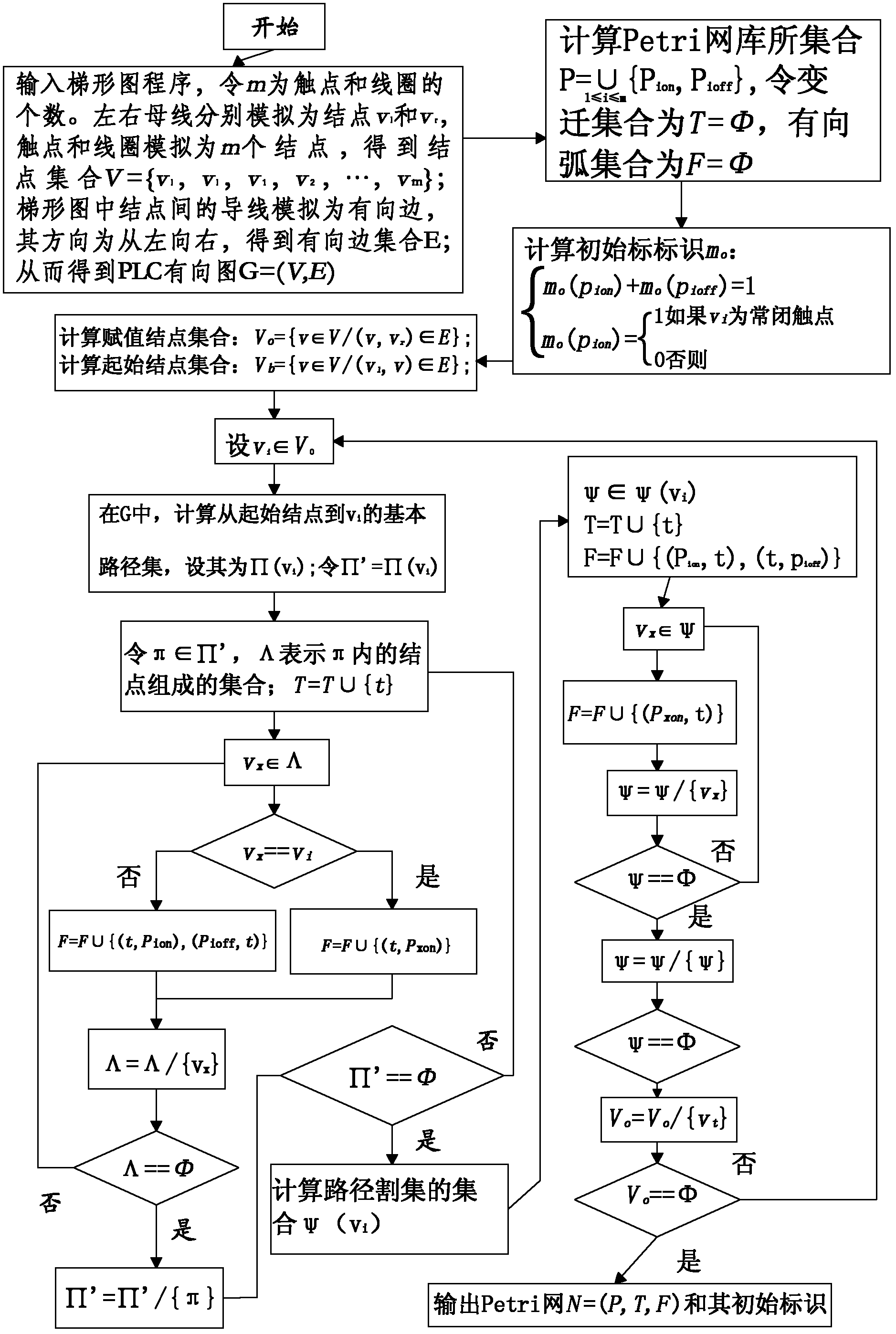
The invention provides a method for converting a PLC program into a common Petri net. The method is characterized by: aiming at a PLC ladder diagram program, simulating a ladder diagram contact and a coil as a node; simulating a lead as a directed edge; establishing a PLC directed graphical model of the ladder diagram program; defining a path in a directed graph; according to a path relation, converting the PLC directed graph into the Petri net. In the invention, automatic conversion from the PLC ladder diagram program to a common Petri net model can be realized. Because an excitation condition of the common Petri net is concise, a logic thinking mode is simple, visual and understandable and the obtained Petri net model can complete simulate a dynamic behavior of a PLC control system, PLC program analysis and error correction can be conveniently achieved and PLC program logic is more precise.

Description

technical field [0001] The invention relates to a mathematical modeling method of a programmable logic controller (PLC) program, which is a powerful tool for PLC program simulation and verification, especially a method for converting a programmable logic controller program into a common Petri net. technical background [0002] Programmable logic controller (PLC) is a typical controller hardware in industrial control systems, widely used in the monitoring of steel, petroleum, chemical, electric power and transportation systems. However, the development of PLC programs faces high complexity problems: with the support of fieldbus technology, the scale and structure complexity of industrial control systems grow rapidly, such as subway traffic control systems and nuclear power control systems, etc., and the number of states of the system varies with the number of sensors The number of and executive agencies is increasing exponentially, and the state of the logistics system consis...

Claims


Application Information

Patent Timeline
Patent Type & Authority Applications(China)
IPC IPC(8): G05B19/05
Inventor 罗继亮陈雪琨齐鹏飞
Owner HUAQIAO UNIVERSITY
Learn More