
Voltage-regulating winding structure of splitting winding type on-load tap-changing transformer

A voltage regulating transformer and voltage regulating winding technology, applied in the direction of transformer/inductor coil/winding/connection, transformer, variable transformer, etc., can solve the problems of large number of lead wires, unfavorable design and manufacture, etc. Easy-to-wind effect

Inactive Publication Date: 2012-04-11
BAODING TIANWEI GRP CO LTD
View PDF4 Cites 2 Cited by
  • Summary
  • Abstract
  • Description
  • Claims
  • Application Information

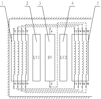
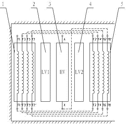
AI Technical Summary

Problems solved by technology

[0002] BACKGROUND OF THE INVENTION The voltage regulating winding of a split transformer is divided into inner and outer parts. The structure of the voltage regulating winding of this type of transformer is a series or parallel structure in which each level of voltage regulation is connected to the inner and outer voltage regulating windings. The problem is: The number of wires is large, which is not conducive to design and manufacture

Method used


Image

  • Voltage-regulating winding structure of splitting winding type on-load tap-changing transformer
  • Voltage-regulating winding structure of splitting winding type on-load tap-changing transformer

Examples


Embodiment Construction

[0010] The present invention will be further described through the embodiments below in conjunction with the accompanying drawings.

[0011] A voltage regulating winding structure of a split on-load voltage regulating transformer. There are five windings on the iron core of the transformer. 3—outer low-voltage winding 4—outer voltage regulating winding 5; The voltage winding is serially connected to the end of the high voltage winding step by step. When the inner voltage regulating winding and the outer voltage regulating winding are all connected in series to the end of the high voltage winding step by step, the high voltage voltage of the transformer is at the limit tap. The wiring characteristics of the said voltage regulating winding are: the internal voltage regulating winding and the external voltage regulating winding are interleaved and connected in series at the end of the high voltage winding step by step. This embodiment is an eight-stage voltage regulation structu...


PUM


Abstract

The invention relates to a voltage-regulating winding structure of a splitting winding type on-load tap-changing transformer, belonging to the technical field of transformers. In a technical scheme, for a winding arrangement sequence, an iron core-inner voltage-regulating winding (1), an inner low-voltage winding (2), a high-voltage winding (3), an outer low-voltage winding (4) and an outer voltage-regulating winding (5) are sequentially arranged from inside to outside, wherein the inner voltage-regulating winding and the outer voltage-regulating winding are symmetrically distributed at two sides of the high-pressure winding by taking the high-voltage winding as a center; the inner voltage-regulating winding and the outer voltage-regulating winding are sequentially and serially arranged into the tail end of the high-voltage winding stage by stage; and when the inner voltage-regulating winding and the outer voltage-regulating winding are sequentially and serially arranged into the tailend of the high-voltage winding completely stage by stage, the high voltage of the transformer is of limit tapping. In the invention, each stage of voltage regulation is unnecessary to realize by bridging the inner and outer two voltage-regulating windings, and the inner and outer voltage-regulating windings are sequentially and serially arranged into the high-voltage winding stage by stage according to odd number and even number; and the number of lead-out conductor wires of the voltage-regulating windings is reduced by half, the occupied space is effectively reduced, the wire outgoing of the voltage-regulating windings is facilitated, the manufacturing difficulty in the process is reduced, and the safe reliability in production operation is increased.

Description

technical field [0001] The invention relates to a voltage regulating winding structure of a split on-load voltage regulating transformer, which belongs to the technical field of transformers. Background technique [0002] BACKGROUND OF THE INVENTION The voltage regulating winding of a split transformer is divided into inner and outer parts. The structure of the voltage regulating winding of this type of transformer is a series or parallel structure in which each level of voltage regulation is connected to the inner and outer voltage regulating windings. The problem is: The large number of wires is not conducive to design and manufacture. Contents of the invention [0003] The purpose of the present invention is to provide a split voltage regulating winding structure of the on-load voltage regulating transformer, so that the number of leading wires of the voltage regulating winding is halved, which effectively reduces the space occupation, facilitates the outgoing line, red...

Claims


Application Information

Patent Timeline
IPC IPC(8): H01F29/02H01F27/28H01F27/29
Inventor 李程张栋杜振斌刘力强张雄何丽颖
Owner BAODING TIANWEI GRP CO LTD
Learn More