Cable connection structure and cable connection method

一种电缆连接、同轴电缆的技术,应用在导电连接、连接、固定连接等方向,能够解决电缆导体短路、电缆导体无法完全容纳等问题,达到操作性及功能性提高的效果

Inactive Publication Date: 2012-04-11
PROTERIAL LTD
View PDF6 Cites 10 Cited by
  • Summary
  • Abstract
  • Description
  • Claims
  • Application Information

AI Technical Summary

Problems solved by technology

As a result, a plurality of cable conductors cannot be completely accommodated in the cable positioning groove, for example, enter the adjacent cable positioning groove, thereby causing a problem of short-circuiting with the adjacent cable conductors.

Method used


Image

  • Cable connection structure and cable connection method
  • Cable connection structure and cable connection method
  • Cable connection structure and cable connection method

Examples


no. 1 approach

[0037] (Structure of multi-core cable)

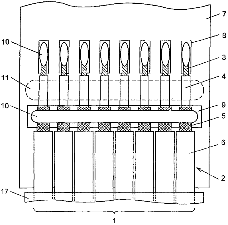
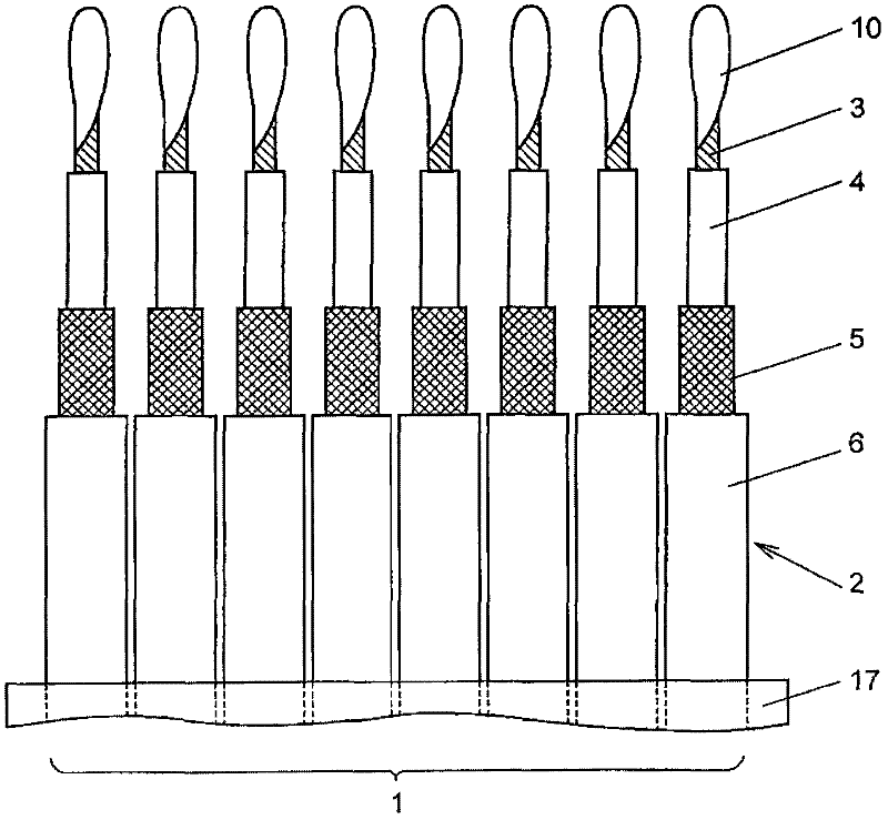
[0038] exist figure 1 In , reference numeral 1 representing the whole is a multi-core cable arranged on a printed circuit board 7 (hereinafter referred to as "substrate 7"). The illustrated multi-core cable 1 is configured by arranging eight ultra-fine coaxial cables 2 in parallel at an arrangement pitch of 0.15 mm and integrally covering them with an insulating laminated tape 17 .

[0039] Such as figure 1 As shown, eight ultra-fine coaxial cables 2 constituting the multi-core cable 1 are integrally formed by the following components: a central conductor 3 whose outer diameter becomes 0.03 mm by twisting seven core wires with a diameter of 0.01 mm; An inner insulator 4 with an outer diameter of 0.06mm on the outer periphery of the center conductor 3; a core wire covering the outer periphery of the inner insulator 4 and having an outer diameter of 0.016mm constitutes an outer conductor 5 with an outer diameter of 0.1mm around the shield...

no. 2 approach

[0066] Below, refer to Figure 2 ~ Figure 6 , the cable connection method for obtaining the cable connection structure of the above-mentioned first embodiment will be described in detail by citing specific embodiments. In addition, in this second embodiment, a typical example of the above-mentioned first embodiment was given, but of course the present invention is not limited to the illustrated example.

[0067] (end processing of multi-core cables)

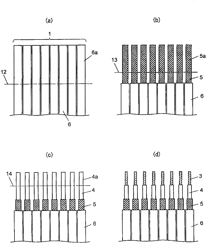
[0068] Before the eight ultra-fine coaxial cables 2 integrated with the laminate tape 17 are electrically connected to the signal electrodes 8 and the ground electrodes 9 of the substrate 7, the sheath cutting process, the outer conductor cutting process, and the inner insulator In each end processing process of cutting processing, CO 2 The end processing of the multi-core cable 1 is performed by laser or YAG laser. According to the preferred mode, it is possible to use image 3 The end-finishing process shown effectively yie...


PUM


Abstract

A cable connection structure includes a multi-core coaxial cable connected to a board. The multi-core coaxial cable (2) includes a plurality of parallel-arranged coaxial cables each including a center conductor (3) and an inner insulator (4), an outer conductor (5) and an outer insulator sequentially formed on an outer periphery of the center conductor. The board includes a signal electrode (8) connected to the center conductor (3) and a ground electrode (9) connected to the outer conductor (5). The cable connection structure further includes a positioning member (11) lying between the signal electrode (8) and the ground electrode (9) for positioning the center conductor (3) while the inner insulator is attached to the positioning member.

Description

technical field [0001] The present invention relates to a cable connection structure and a cable connection method for connecting a central conductor of a cable to an electrode formed on a printed circuit board or the like. Background technique [0002] In recent years, in the field of electrical and electronic equipment, for example, miniaturization and weight reduction of various terminal devices such as notebook computers and mobile phones have been demanded. These terminal devices have a structure in which an upper case including a liquid crystal display unit and a lower case including a control device are connected and fixed by a three-dimensionally movable hinge portion, thereby improving operability, functionality, and the like. [0003] In such a terminal device, it is necessary to transmit and receive electrical signals between the upper housing and the lower housing through a three-dimensionally movable hinge portion. Therefore, a three-dimensionally movable cable...

Claims


Application Information

Patent Timeline
Patent Type & Authority Applications(China)
IPC IPC(8): H01R12/53H01R43/00
CPCH01R9/0515H01R4/027Y10T29/49123
Inventor 田中康太郎矢口昭弘小山洋
Owner PROTERIAL LTD
Why Eureka
Try Eureka