Multi-channel load drive circuit

A technology for driving circuits and multi-channel loads, which is applied in the direction of lamp circuit layout, electric light sources, lighting devices, etc., and can solve the problems of high cost and large loss

Inactive Publication Date: 2012-04-11
马丽娟
View PDF5 Cites 1 Cited by
  • Summary
  • Abstract
  • Description
  • Claims
  • Application Information

AI Technical Summary

Problems solved by technology

[0002] In many applications, multiple loads need to be driven at the same time, and the current of each load is required to be the same. The traditional method is to use a current adjustment unit in each load, so that the current of each load is the set value, reaching The purpose of the same current, for example, in order to make multiple light-emitting diodes emit light at the same time, in order to achieve the purpose of the same characteristics of light-emitting diodes, each light-emitting diode LED is required to have an equal operating current. The prior art requires the use of multiple current adjustment units, and there is a loss Disadvantages of large size and high cost, refer to figure 1

Method used


Image

  • Multi-channel load drive circuit
  • Multi-channel load drive circuit
  • Multi-channel load drive circuit

Examples


Embodiment Construction

[0031] Some typical embodiments embodying the features and advantages of the present invention will be described in detail in the description in the following paragraphs. It should be understood that the present invention can have various changes in different aspects without departing from the scope of the present invention, and that the description and drawings therein are illustrative in nature rather than limiting the present invention.

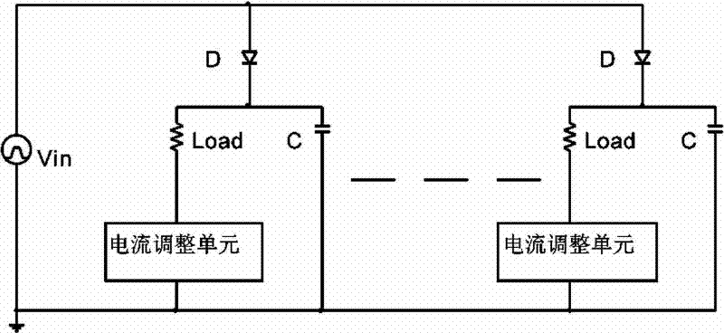
[0032] see Figure 5 , which is a schematic diagram of the circuit architecture of the first preferred embodiment of the present invention, such as Figure 5 As shown, this embodiment is a six-way load driving circuit. This circuit includes: input power Vin, five coupling capacitors, and a series branch X. The connection method is: the first end and the tail end of the series branch X are connected to the common line, The series node XJ1 of the series branch X is connected to the coupling capacitor C0-1, the series node XJ2 is connected t...


PUM


Abstract

The invention aims at providing a multi-link-load drive circuit which is capable of reducing loss and cost and balancing the current of a multi-channel load. The multi-link-load drive circuit comprises a series branch X, coupling capacitors, and an input power supply Vin, and can also comprises an additional voltage Vf.

Description

technical field [0001] The invention relates to a drive circuit for multiple loads with the same current magnitude. Background technique [0002] In many applications, multiple loads need to be driven at the same time, and the current of each load is required to be the same. The traditional method is to use a current adjustment unit in each load, so that the current of each load is the set value, reaching The purpose of the same current, for example, in order to make multiple light-emitting diodes emit light at the same time, in order to achieve the purpose of the same characteristics of light-emitting diodes, each light-emitting diode LED is required to have an equal operating current. The prior art requires the use of multiple current adjustment units, and there is a loss Disadvantages of large size and high cost, refer to figure 1 . Contents of the invention [0003] The main purpose of the present invention is to provide a multi-channel load drive circuit that reduce...

Claims


Application Information

Patent Timeline
Patent Type & Authority Applications(China)
IPC IPC(8): H02M7/04H05B37/02
Inventor 马丽娟
Owner 马丽娟
Why Eureka
Try Eureka