Permanent magnet bearing-free auto-suspension three-degree-of-freedom spherical motor and control method thereof

A spherical motor, bearingless technology, applied in the direction of electrical components, magnetic attraction or thrust holding device, etc., can solve the problems of reducing friction, strong pressure, damage to the rotor surface, etc., to simplify design, improve motion characteristics, The effect of improving flexibility

Active Publication Date: 2012-04-11
TIANJIN UNIV
View PDF5 Cites 33 Cited by
  • Summary
  • Abstract
  • Description
  • Claims
  • Application Information

AI Technical Summary

Problems solved by technology

There are some problems in these contact methods. In the direct contact method, the rotor is directly placed on the inner wall of the stator or on the slip ring. Although the coating with a low friction coefficient is used to reduce the sliding friction, the friction torque will still be generated by the movement of the rotor. Impact, as mentioned in patent 200810053083.5; the universal ball bearing uses rolling friction instead of sliding friction, although the friction torque is reduced, but because the bearing and the rotor are in point contact, the pressure is high, and the rotor surface may be damaged; The joint bearing can better realize the three-degree-of-freedom movement of the rotor, but this kind of bearing is more suitable for the low-speed movement of the motor; the air bearing can realize the non-contact between the stator and the rotor, which greatly reduces the friction, but requires additional air pressure device

Method used


Image

  • Permanent magnet bearing-free auto-suspension three-degree-of-freedom spherical motor and control method thereof
  • Permanent magnet bearing-free auto-suspension three-degree-of-freedom spherical motor and control method thereof
  • Permanent magnet bearing-free auto-suspension three-degree-of-freedom spherical motor and control method thereof

Examples


Embodiment Construction

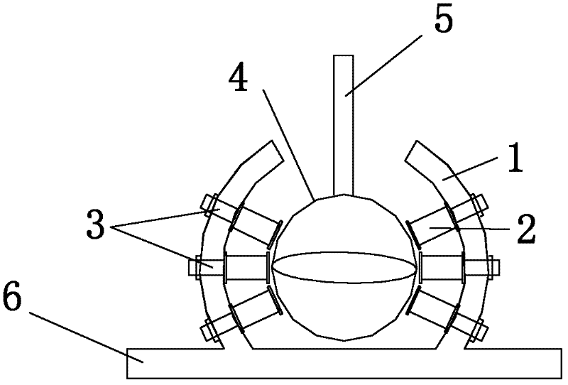
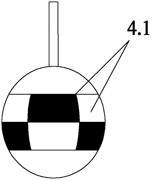
[0025] The permanent magnet bearingless self-suspending three-degree-of-freedom spherical motor includes a supporting part, a stator and a spherical rotor sensor. The supporting part includes a stator wall 1, a base 6, a stator including a hollow coil 2, a coil bolt (3), and a spherical rotor 4. 上fix the output shaft 5. The basic structure of the motor is as figure 1 Shown. Permanent magnet poles 41 are pasted on the surface of the rotor. The poles are divided into upper and lower layers along the equator. Each layer has 6 poles. Each layer has alternate N and S poles, and the upper and lower layers alternate N and S poles. Such as figure 2 Shown.

[0026] When the stator winding is energized, the electromagnetic force received by the winding will contain a radial component and a tangential component. The radial component of the electromagnetic force does not produce electromagnetic torque, but it can cause the rotor to shift in position. Before the motor runs, the rotor is sup...


PUM


Abstract

The invention belongs to the technical field of design and control of motors and relates to a permanent magnet bearing-free auto-suspension three-degree-of-freedom spherical motor. The permanent magnet bearing-free auto-suspension three-degree-of-freedom spherical motor comprises a base, a spherical stator wall, stator coils and a rotor, wherein the rotor is positioned in the stator wall; the output shaft of the rotor extends out of an opening above the stator wall; the spherical motor is characterized in that: the stator coils have columnar ironless structures; three layers of stator coils are uniformly distributed along the equator of the spherical stator wall and wefts parallel to the equator and radially fixed on the spherical stator wall; permanent magnet poles are embedded on the surface of the rotor and divided into two layers, namely an upper layer and a lower layer, along the equator; the poles N and the poles S on each layer are staggered; and each stator coil is independently controlled by a driving circuit. The invention also provides a control method for the motor. By the motor and the control method thereof, controllability of a magnetic suspension force and bearing-free running of the motor are realized; furthermore, the movement characteristic of the motor and the flexibility of design of a motor control system are improved.

Description

Technical field [0001] The invention belongs to the technical field of motor design and control, and relates to a multi-degree-of-freedom spherical motor. Background technique [0002] With the advancement of science and technology, the application range of multi-degree-of-freedom motion mechanisms has become wider and wider. The traditional multi-degree-of-freedom motion mechanism is realized by multiple single-degree-of-freedom motors, which is huge, low in transmission accuracy, and difficult to control. The spherical motor can realize the movement of the rotor with three degrees of freedom, and has a wide range of application prospects in high-precision control systems such as robots and nano working platforms. The permanent magnet spherical motor also has the characteristics of small size and high torque density. [0003] Due to the special structure and movement mode, the support device of the spherical motor rotor is also different from ordinary motors. In the structural s...

Claims


Application Information

Patent Timeline
Patent Type & Authority Applications(China)
IPC IPC(8): H02N15/00
Inventor 夏长亮李斌李桂丹史君杰
Owner TIANJIN UNIV
Why Eureka
Try Eureka