Three-dimensional wave beam forming method in long term evolution (LET)

A three-dimensional beam-forming technology, applied in space transmit diversity, diversity/multi-antenna systems, etc., can solve problems such as impact on user service experience, difficulty in beam scheduling and interference coordination, and reduction in receiving power

Active Publication Date: 2012-04-11
天元瑞信通信技术股份有限公司
View PDF2 Cites 132 Cited by
  • Summary
  • Abstract
  • Description
  • Claims
  • Application Information

AI Technical Summary

Problems solved by technology

[0004] The solution of fixed downtilt angle can improve the throughput of the cell to a certain extent, but because this technology adopts the same downtilt angle for all users in the cell, the main lobe of the radiation pattern of the antenna can only be aligned with a certain one in the cell. direction, while the received power of other users deviating from the main lobe will be reduced, which will affect the service experience of these users
In addition, the method of providing fixed beams in the vertical direction makes it difficult to achieve beam scheduling and interference coordination between adjacent cells in the vertical direction, which brings obstacles to further reducing interference between adjacent cells

Method used


Image

  • Three-dimensional wave beam forming method in long term evolution (LET)
  • Three-dimensional wave beam forming method in long term evolution (LET)
  • Three-dimensional wave beam forming method in long term evolution (LET)

Examples


Embodiment 1

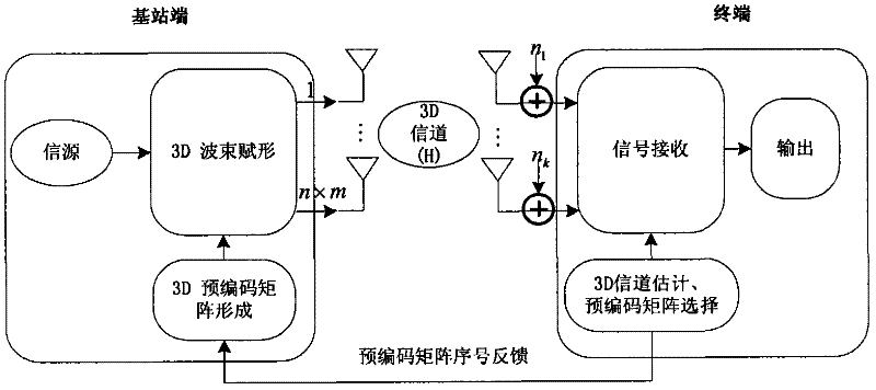
[0050] System block diagram of 3D beamforming technology based on precoding under 3D channel, such as figure 1 , mainly including signal reception, 3D channel estimation, horizontal and vertical dimension precoding matrix selection, precoding matrix serial number feedback, 3D beamforming weight formation, 3D beamforming signal transmission and reception and other modules.

[0051] The specific implementation steps of the 3D beamforming method based on precoding under the 3D channel proposed by the present invention include the following:

[0052] Step 1. The base station adopts an array antenna structure, and each antenna in the vertical direction is connected to a port that can be used for beamforming, so that the forming weights of each antenna array element can be adjusted, and the matrix W n×m Represents the weight matrix, where n represents the number of rows of the antenna array, m represents the number of columns of the antenna array, and the receiving end uses k receiv...

Embodiment 2

[0077] The invention improves the overall performance of the system by optimizing the shaping weights of the antenna in the horizontal and vertical directions and simultaneously obtaining the shaping gains in the horizontal and vertical directions. The beneficial effects brought by the present invention can be further illustrated by simulation and theoretical analysis:

[0078] The configuration of simulation parameters is shown in Table 1.

[0079]Table 1 Simulation parameter configuration

[0080] simulation time

1000ms

channel type

3D SCM

ISD (Inter-Site Distance) cell distance

500m

system bandwidth

10MHz

Base station antenna spacing

Horizontal 10λ Vertical 0.5λ

The number of antennas at the transmitting end

4×4

The number of antennas at the receiving end

1

Number of districts

19 (3 ​​circles)

sector

3 sectors per cell

Number of users requesting service per sect...


PUM


Abstract

The invention discloses a three-dimensional wave beam forming method in long term evolution (LET). The three-dimensional wave beam forming method comprises the following steps that: a base station adopts an array antenna structure, and each antenna in the vertical direction has a port for wave beam forming; a terminal receives a signal, performs channel estimation to acquire a three-dimensional (3D) channel matrix H and selects a horizontal-dimension precoding matrix and a vertical-dimension precoding matrix according to the H; the terminal feeds sequence numbers corresponding to the precoding matrixes selected in the step 2 back to the base station, and the base station recovers the corresponding horizontal-dimension precoding matrix and the corresponding vertical-dimension precoding matrix according to the fed sequence numbers, and generates a 3D precoding matrix; and the base station precodes the sent signal according to the precoding matrix obtained in the step 3, performs 3D wave beam forming on the sent signal and sends the processed signal through the antenna, and the terminal receives the signal and returns to the step 2. By the method, channel information in the horizontal direction and the vertical direction are used comprehensively, and horizontal-dimension wave beam forming and vertical-dimension wave beam forming are realized at the same time, so higher wave beam forming gain can be obtained and the whole performance of the system can be improved.

Description

technical field [0001] The present invention relates to the technical field of wireless communication, in particular to a three-dimensional beamforming method in LTE (Long Term Evolution, long-term evolution). Background technique [0002] Beamforming technology is widely used in wireless communication systems. Its main task is to compensate for signal fading and distortion caused by factors such as space loss and multipath effects during wireless propagation, while reducing interference between co-channel users and improving system capacity. . Existing beamforming technology can only realize the movement of the beam following the target user in the horizontal direction by controlling the beamforming weights of the horizontal antenna elements, which can be regarded as tracking in two-dimensional space. The shaping weight in the vertical direction is a fixed value, that is, the beam in the vertical direction is fixed, so it is impossible to track the user in the vertical dir...

Claims


Application Information

Patent Timeline
Patent Type & Authority Applications(China)
IPC IPC(8): H04B7/06
Inventor 李晓辉吴极张金钊
Owner 天元瑞信通信技术股份有限公司
Why Eureka
Try Eureka