Buffering and damping device for automobile engine

A technology for automobile engines and shock absorbers, which is applied in power units, jet propulsion devices, internal combustion propulsion devices, etc., can solve problems such as opening of glue, no excessive restriction on deformation amount, cracking of glue, etc. Convenience and the effect of reducing investment

Inactive Publication Date: 2012-04-18
姜言义
View PDF6 Cites 7 Cited by
  • Summary
  • Abstract
  • Description
  • Claims
  • Application Information

AI Technical Summary

Problems solved by technology

[0004] Chinese Patent No. ZL200920045307.8 once disclosed a new type of shock absorber for an engine, which includes an engine frame, an upper shock absorber, a vehicle frame, a lower shock absorber, bolts and nuts, wherein the upper shock absorber It is composed of steel pipe, rubber and seat ring, the steel pipe is set inside the rubber, the seat ring is fixed at the bottom of the rubber, the lower shock absorber and the upper shock absorber are arranged symmetrically, and the upper shock absorber and the lower shock absorber respectively pass through the seat ring Connected with the frame, the bolts pass through the steel pipes in the middle of the upper and lower shock absorbers respectively and are fixed on the engine frame by nuts. There is still a gap between the upper and lower shock absorbers. Although the new engine shock absorber can pass through The rubber and the gaps in the middle play a role in shock absorption, but since the device does not limit the deformation of the rubber too much, the rubber will open and crack after working for a long time

Method used


Image

  • Buffering and damping device for automobile engine
  • Buffering and damping device for automobile engine
  • Buffering and damping device for automobile engine

Examples


Embodiment Construction

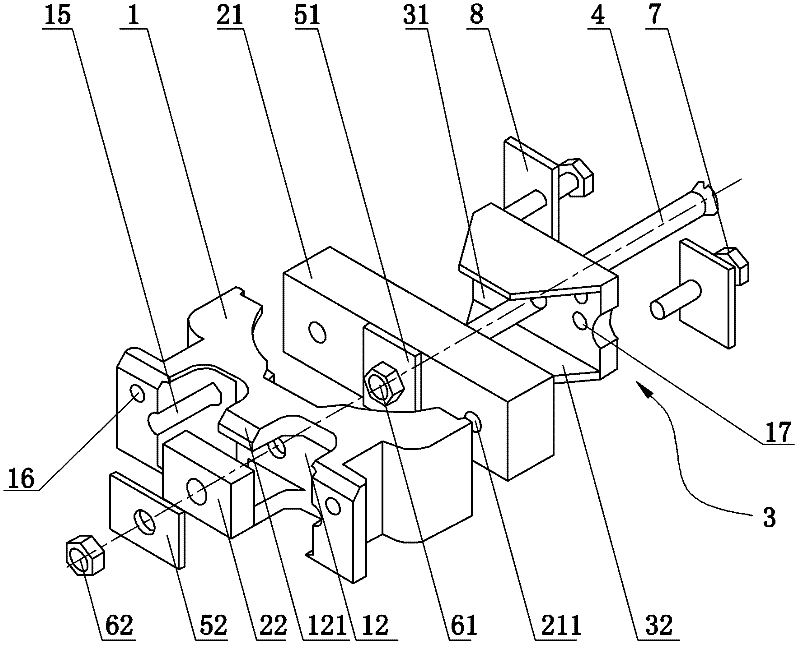
[0020] Such as figure 1 As shown, it is an assembly diagram of an embodiment of the automobile engine buffer and shock absorber of the present invention. The automobile engine buffer and shock absorber includes a base 1, and the base 1 is detachably fixed on the vehicle frame. The fixing method can be A vehicle frame connecting hole 16 is opened on the base 1, and is fixed on the vehicle frame by bolts.

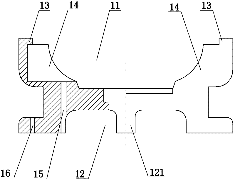
[0021] The upper surface of the base 1 is provided with an upper groove 11, and an upper rubber block 21 for buffering and shock absorption is arranged in the upper groove 11, and opposite probes are arranged at both ends of the upper groove 11. Protruding portion 13, the protruding portion 13 is pressed and buckled on the two ends of the upper rubber block 21 respectively, and an upper recess in contact with the upper rubber block 21 is also provided on both sides of the upper groove 11 Groove guard plate 14, like this, described protruding portion 13 and upper groove guard...


PUM


Abstract

The invention discloses a buffering and damping device for an automobile engine. The buffering and damping device comprises a base, an upper rubber block and a lower rubber block, wherein the base is detachably connected with a frame; the upper rubber block and the lower rubber block play a role in buffering and damping; the upper surface of the base is provided with an upper groove; the upper rubber block is arranged in the upper groove; the lower surface of the base is provided with a lower groove; the lower rubber block is arranged in the lower groove; the upper rubber block is covered with a fixing cover; the fixing cover is detachably connected with the engine; a middle bolt passes through the centers of the fixing cover, the upper rubber block, the base and the lower rubber block; the upper rubber block is pressed against the inside of the fixing cover through an upper glue clamping steel plate which is sleeved on the middle bolt; and the lower rubber block is pressed against the inside of the lower groove through a lower glue clamping plate which is sleeved on the middle bolt. Due to the adoption of a mechanical combined installation process for the buffering and damping device, convenience is brought to production and processing, high working stability is realized, a certain damaged component can be replaced separately, and the cost investment is greatly reduced.

Description

technical field [0001] The invention relates to the field of engine buffer equipment, in particular to an automobile engine buffer and shock absorber. Background technique [0002] When the car engine is working, it will produce continuous and frequent vibrations due to the rotation impact of the crankshaft. If the engine is directly installed on the frame, it will cause damage to the engine due to the rigid connection between the two, especially when driving on roads. In good industrial machinery and agricultural machinery, the damage of the engine is particularly obvious. Once the engine falls off the frame, it will cause serious safety hazards. [0003] The engine buffer and shock absorbing device in the prior art is generally bonded and fixed by vulcanized rubber to two pieces of cast iron, and then these two pieces of cast iron are respectively fixed on the engine and the vehicle frame, relying on the elasticity of the vulcanized rubber to buffer and shock absorb the en...

Claims


Application Information

Patent Timeline
Patent Type & Authority Applications(China)
IPC IPC(8): B60K5/12
Inventor 姜靖涛
Owner 姜言义
Why Eureka
Try Eureka