Spraying apparatus for metal-organic chemical vapor deposition equipment

A chemical vapor deposition and organic compound technology, which is applied in gaseous chemical plating, metal material coating process, coating, etc., can solve the problems of poor uniform mixing effect and achieve uniform mixing effect

Inactive Publication Date: 2012-04-25
彭继忠
View PDF4 Cites 19 Cited by
  • Summary
  • Abstract
  • Description
  • Claims
  • Application Information

AI Technical Summary

Problems solved by technology

Although the spray device with this structure can realize the independent delivery of two channels of gas, the two channels of gas are transported to the surface of the wafer in the way that the first delivery channel and the second delivery channel are staggered. When the two channels of ...

Method used


Image

  • Spraying apparatus for metal-organic chemical vapor deposition equipment
  • Spraying apparatus for metal-organic chemical vapor deposition equipment
  • Spraying apparatus for metal-organic chemical vapor deposition equipment

Examples


Embodiment 1

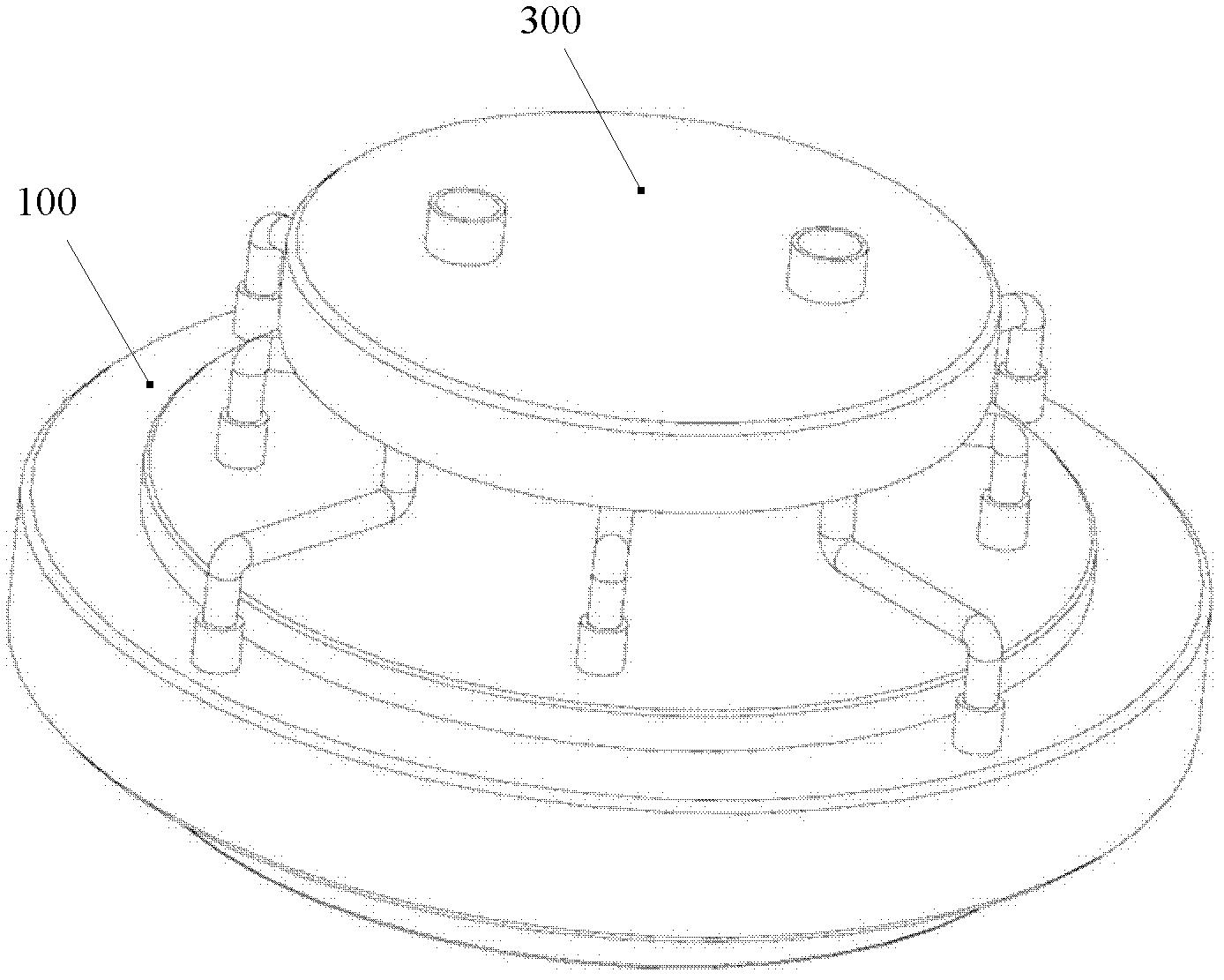
[0035] Figure 1A It is a schematic diagram of the connection structure between the embodiment of the present invention and the gas distribution unit. A gas distribution unit 300 is connected to the upper end of the shower device used in metal organic compound chemical vapor deposition equipment of the present invention.

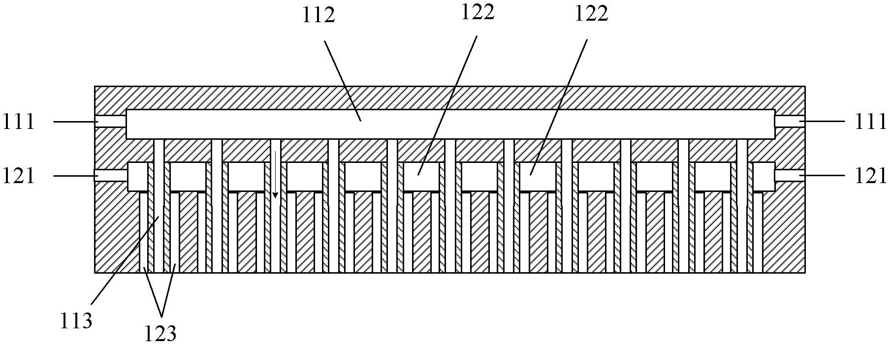
[0036] Figure 1B It is a sectional view of Embodiment 1 of the present invention.

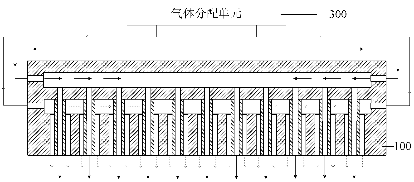
[0037] Figure 1C It is a schematic diagram of gas flow in Example 1 of the present invention.

[0038] Figure 2A It is a schematic diagram of a partial cross-sectional structure of Embodiment 1 of the present invention.

[0039] Figure 2B It is a top sectional view of nested structures arranged in parallel in Embodiment 1 of the present invention.

[0040] Please refer to Figure 1A , 1B , 1C, 2A, 2B, this embodiment 1 is used for the spraying device of metal organic compound chemical vapor deposition equipment, using two conveying channels, including a first air i...

Embodiment 2

[0049] Figure 3A It is a schematic diagram of a partial cross-sectional structure of Embodiment 2 of the present invention.

[0050] Figure 3B It is a top sectional view of nested structures arranged radially in Embodiment 2 of the present invention.

[0051] Please refer to Figures 3A to 3B , this embodiment 2 is improved on the basis of embodiment 1, and the difference is that: the second through holes 123 are arranged in a radial structure instead of in a parallel structure.

[0052] For the nested structure of Example 2, please refer to Figure 3A The part in the dotted box and Figure 3B .

Embodiment 3

[0054] Figure 4 It is a top sectional view of a nested structure arranged in a circle in Embodiment 3 of the present invention. Embodiment 3 is improved on the basis of Embodiment 1 or 2, and the difference is that: the second through holes 123 are arranged in a circular structure instead of radial or parallel. That is, the second through hole 123 expands outward round by round. The first through holes 113 are evenly distributed in the second through holes 123 in each circle.

[0055] Figure 5 It is a three-dimensional schematic diagram of the nested structure of the above two or three embodiments 1, 2 and 3. Please refer to Figure 5 , the nested structure of each second through hole 123 and its corresponding plurality of first through holes 113 , that is, each second through hole 123 nests a plurality of first through holes 113 . The first through hole 113 may be a circular hole, a square hole or a triangle, etc., and the second through hole 123 is a slot-shaped hole....


PUM


Abstract

The present invention discloses a spraying apparatus for metal-organic chemical vapor deposition (MOCVD) equipment. The apparatus comprises at least two transportation channels. Each transportation channel comprises air inlets, a cavity and through holes, wherein the air inlets, the cavity and the through holes are communicated. The positions between the through holes of all the transportation channels are the nested structures. According to the present invention, the uniform mixing effect of a plurality of gases can be improved by the spraying apparatus for the MOCVD equipment.

Description

technical field [0001] The invention relates to the technical field of semiconductor manufacturing, in particular to a spray device used for metal organic compound chemical vapor deposition equipment. Background technique [0002] Metal-organic Chemical Vapor Deposition Metal-organic Chemical Vapor Deposition, MOCVD, is used in the field of semiconductor manufacturing technology to deposit thin films. [0003] MOCVD uses organic compounds of Group III and II elements and hydrides of Group V and VI elements as wafer growth materials, and performs vapor phase epitaxy on the substrate in a thermal decomposition reaction mode to grow various III-V, II - Thin-layer single-crystal materials of Group VI compound semiconductors and their multi-component solid solutions. That is to say, in the MOCVD process, at least two gases are used. [0004] The reaction chamber is a main component of the MOVCD equipment. It mainly transmits two or more than two kinds of gases into the reaction...

Claims


Application Information

Patent Timeline
IPC IPC(8): C23C16/455
Inventor 彭继忠
Owner 彭继忠
Why Eureka
Try Eureka