Large steel structure heel embedded part positioning device and method

A positioning device and steel structure technology, which are applied in basic structure engineering, construction and other directions, can solve the problems of tilting of bolt rods, difficult to realize the positioning of the bottom end of bolts embedded in column feet, etc., and achieve the effects of easy production, simple structure and low cost.

Active Publication Date: 2012-04-25
CHINA THIRD METALLURGICAL GRP
View PDF4 Cites 14 Cited by
  • Summary
  • Abstract
  • Description
  • Claims
  • Application Information

AI Technical Summary

Problems solved by technology

The disadvantage of this method is that after positioning the bolts of the embedded parts, due to the large depth of the reinforcement foundation of the large-scale steel structure, the length of the bolt rod of the embedded part of the column foot inserted into the reinforcement foundation is relatively long, and the bottom of the part where the bolt rod is inserted There is no fastening device at the end, and during the pouring of concrete, due to the fluid nature of the concrete, the bolt shank is inclined
As we all know, two points determine a straight line. How to accurately locate and fasten the bottom end of the bolt rod of the embedded part of the column foot is the key to the precise positioning of the embedded part of the column foot. However, in the existing construction method, due to the After the foundation is bound, the gap between the horizontal and vertical steel bars is small, and the bottom positioning of the embedded bolts at the column base is difficult to achieve

Method used


Image

  • Large steel structure heel embedded part positioning device and method
  • Large steel structure heel embedded part positioning device and method
  • Large steel structure heel embedded part positioning device and method

Examples


Embodiment 1

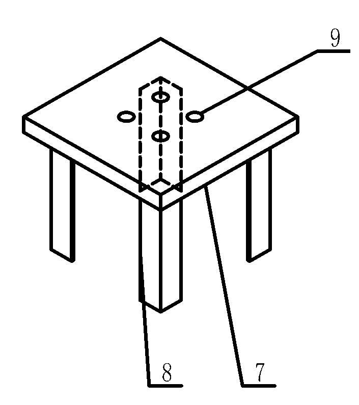
[0027] Embodiment 1, a large-scale steel structure column foot embedded parts positioning device, such as figure 1 As shown, it includes a positioning plate 7 and a connector 8. The positioning plate 7 is provided with a bolt hole 9, and the structure and position of the bolt hole 9 are matched with the pre-positioned column foot embedded parts 4 bolts. The positioning plate One side of 7 is provided with connecting piece 8, and positioning plate 7 is made of thick steel plate, and its thickness is 25mm; , and the length of each connector 8 is 220mm.

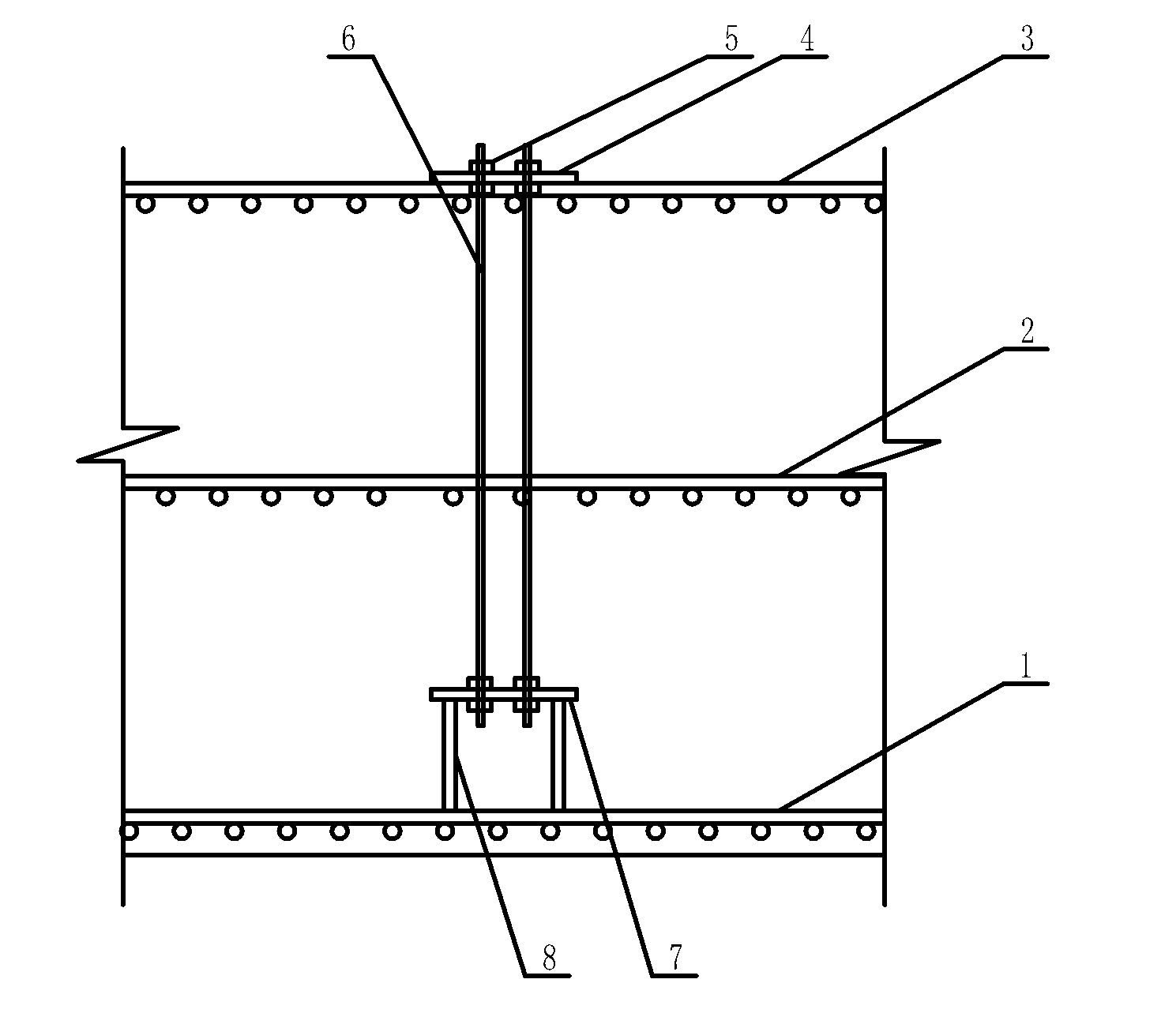
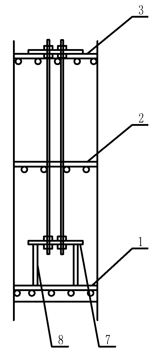
[0028] Positioning method for embedded parts of large steel structure columns, such as figure 2 , image 3 As shown, the method includes the following steps:

[0029] 1) Make the positioning plate 7, according to the diameter and relative position of the pre-installed and positioned column foot embedded parts 4 bolts, take a thick steel plate with a thickness of 25mm, and drill holes on it, so that the bolt holes 9 on the th...

Embodiment 2

[0037] Embodiment 2, large-scale steel structure column foot embedded parts positioning device, such as figure 1 As shown, it includes a positioning plate 7 and a connecting piece 8. The positioning plate 7 is provided with a bolt hole 9. The structure and position of the bolt hole 9 are matched with the pre-positioned column foot embedded parts 4 bolts. The positioning plate One side of 7 is provided with connector 8, and positioning plate 7 is made of thick steel plate, and its thickness is 30mm; , and the length of each connector 8 is 250mm.

[0038] Positioning method for embedded parts of large steel structure columns, such as figure 2 , image 3 As shown, the method includes the following steps:

[0039] 1) Make the positioning plate 7, according to the diameter and relative position of the pre-installed and positioned column foot embedded parts 4 bolts, take a thick steel plate with a thickness of 25mm, and drill holes on it, so that the bolt holes 9 on the thick st...


PUM


Abstract

The invention relates to a large steel structure heel embedded part positioning device and method. The positioning device comprises a positioning plate and connecting members, wherein the positioning plate is provided with a bolt hole, the bolt hole is matched with a pre-positioned heel embedded part bolt in structure and position, and one surface of the positioning plate is provided with at least four or more connecting members. The method comprises the steps of: firstly, binding a low layer of reinforcement bars in a large steel structure foundation; secondly, welding the connecting memberson the lower layer of reinforcement bars, determining the bottom end position of the heel embedded part bolt by using a transit and a leveling instrument, and then binding a middle layer and an upperlayer of reinforcement bars, regulating the upper end position of the bolt by using a plumb bob and the leveling instrument; and finally, fastening the heel embedded part bolt and a heel embedded part. Compared with the prior art, the invention has the beneficial effects of simple structure, convenience for installation and low cost, and ensures that a heel embedded part bolt rod does not inclineor displace in a process of poring concrete so that the heel embedded part is positioned more accurately and the engineering quality is improved.

Description

technical field [0001] The invention relates to a positioning device, in particular to a positioning device and a positioning method for a large-scale steel structure column foot embedded part. Background technique [0002] In the construction of large-scale steel structures, the column foot embedded parts must be installed first. The installation of the column foot embedded parts needs to determine the precise position of the column foot embedded parts. Usually, the bolts of the column foot embedded parts are used to position and fix them, so the column The positioning of the bolts of the foot embedded parts is especially important for the positioning of large steel structures. If the positioning is not accurate, it will cause the installation of the entire large steel structure to fail to proceed smoothly. [0003] In the traditional large-scale steel structure construction, the installation method for the column foot embedded parts is to use the theodolite and level to d...

Claims


Application Information

Patent Timeline
Patent Type & Authority Applications(China)
IPC IPC(8): E02D27/42
Inventor 孙海友
Owner CHINA THIRD METALLURGICAL GRP
Why Eureka
Try Eureka