
Potential difference meter experimental apparatus

A potentiometer and experimental data technology, applied in the direction of educational equipment, instruments, teaching models, etc., can solve the problems that the teacher's experimental mastery cannot have a good understanding, errors are easy to occur, and deviations occur

Inactive Publication Date: 2012-04-25
NORTH CHINA ELECTRIC POWER UNIV (BAODING)
View PDF3 Cites 2 Cited by
  • Summary
  • Abstract
  • Description
  • Claims
  • Application Information

AI Technical Summary

Problems solved by technology

[0003] There are three problems in this kind of experimental process. First, it is not easy to understand the students' experimental mastery. As we all know, plagiarism among students is common. If students plagiarize other people's experimental data after the experiment, and use it Submitting the experiment report, the experiment teacher can't find out in time, because the student's data recording process is completely independent of the teacher, the result is that the teacher can't have a good understanding of the student's experimental mastery, which leads to the lack of confidence in teaching. There are deviations in quality assessment; second, students spend time and effort in the process of data recording, and the data are separated from each other, which is prone to errors; third, experimental teachers rely on experience to process student data, which inevitably occurs during the scoring process. deviation

Method used


Image

  • Potential difference meter experimental apparatus
  • Potential difference meter experimental apparatus
  • Potential difference meter experimental apparatus

Examples


Embodiment Construction

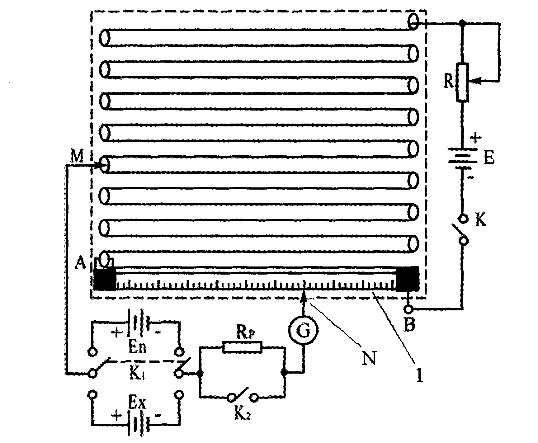
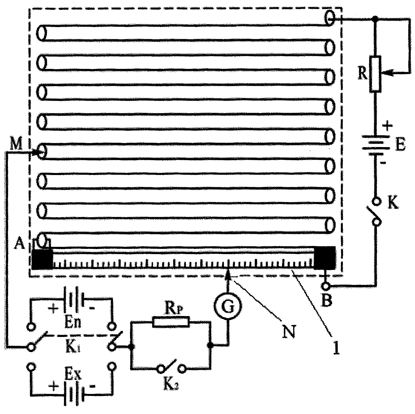
[0012] figure 1 The schematic circuit diagram of the potentiometer experiment in the present invention is shown, and this part is consistent with the potentiometer in the prior art. In the present invention, an electronic digital caliper 2 is additionally installed between the sliding contact N and the scale 1.

[0013] The present invention is characterized in that it also includes data collection, transmission and reception modules. Students move the sliding contact N, when the current in the galvanometer G is 0, press the "record" button on the circuit board embedded with the single-chip microcomputer, the single-chip microcomputer automatically reads the reading of the electronic digital caliper, obtains the length of the resistance wire, and The data is transmitted to a display connected to it, and a "send" button and a bluetooth transmitter module are also arranged on the circuit board embedded with a single-chip microcomputer, by pressing the "send" button, the bluetoot...


PUM


Abstract

The invention discloses an acquiring, transmitting and real-time processing apparatus of experimental data of a potential difference meter. The apparatus comprises a potential difference meter board, a galvanometer, a circuit board embedded with a single-chip, a Bluetooth transmission module, a display and a computer used for collection and real-time processing of the experimental data and configured with a Bluetooth reception module. The apparatus is characterized in that the potential difference meter experimental apparatus is configured with an electronic digital display caliper which is connected with the single-chip; when a student needs to record data, data content measured by the electronic digital display caliper can be transmitted in real time and displayed on a display which is connected with the single-chip by pressing down a recording button on the circuit board which is embedded with the single-chip; after the student measures all the needed data, a data packet containingthe data as well as the serial number and the name of the student can be transmitted to the computer through the Bluetooth transmission module by pressing down the sending button on the circuit boardwhich is embedded with the single-chip; and then the computer performs subsequent processing on the data.

Description

technical field [0001] The invention relates to a university physics experiment device, mainly relates to a potentiometer experiment data collection, transmission and real-time processing system, and belongs to the field of university physics experiment instruments. Background technique [0002] Potentiometer experiment is one of the basic experiments in college physics experiment teaching, which mainly involves direct and accurate measurement of potential difference in electrical measurement, measurement of battery electromotive force and other experimental content. At present, most colleges and universities in China use sliding wire potentiometers. During the experiment, students read the length of the resistance wire by moving the position of the sliding contact, and record the data on the experimental report paper to calculate the potential difference or Electromotive force of the battery. [0003] There are three problems in this kind of experimental process. First, it...

Claims


Application Information

Patent Timeline
Patent Type & Authority Applications(China)
IPC IPC(8): G09B23/18
Inventor 李松涛任芝
Owner NORTH CHINA ELECTRIC POWER UNIV (BAODING)
Learn More