Coarse grid sunk well for physically processing waste water and construction method thereof

A technology of physical treatment and construction method, applied in separation methods, chemical instruments and methods, caisson and other directions, can solve the problems of high construction technology and risk, large amount of preparatory work, and difficult construction quality control, etc. Reduce risk and improve efficacy

Active Publication Date: 2012-05-02
中铁市政环境建设有限公司
View PDF5 Cites 10 Cited by
  • Summary
  • Abstract
  • Description
  • Claims
  • Application Information

AI Technical Summary

Problems solved by technology

When this method is used for underwater bottom sealing, the water injection depth inside the caisson is large, and divers must be placed below to lay riprap; when the bottom sealing concrete is poured, a conduit guide rail frame must be erected, which requires a large amount of preparation work in the early stage, high technical and risky construction, and difficult control of construction quality. and waste a lot of money
[0004] Domestic patent application No. 201010545965.0 discloses a construction method for sinking super large-scale caissons on land. A floating box working platform is set on the water surface of the compartment of the caisson. , through the high-pressure water gun to wash the soil to form mud and then discharge it outside the caisson. After the soil at the bottom of the caisson is hollowed out, it sinks under the action of the caisson's own gravity. This patent uses semi-drainage to sink, which solves the need to build The problem of huge platform support saves investment, but still does not solve the problem of low work efficiency

Method used


Image

  • Coarse grid sunk well for physically processing waste water and construction method thereof
  • Coarse grid sunk well for physically processing waste water and construction method thereof
  • Coarse grid sunk well for physically processing waste water and construction method thereof

Examples


Embodiment Construction

[0056] The present invention will be further described below with reference to the accompanying drawings.

[0057] 1. Compilation basis

[0058] "Engineering Measurement Specification" (GB 50026-2007)

[0059] "Code for Measurement of Building Deformation" (JGJ 8-2007)

[0060] "Code for Construction and Acceptance of Water Supply and Drainage Structures" (GBJ 141-90)

[0061] "Code for Loading of Building Structures" (GB 50007-2002)

[0062] "Code for Design of Concrete Structures" (GB 50010-2002)

[0063] "Code for Design of Building Foundation" (GB 50007-2002)

[0064] "Design code for reinforced concrete caisson structure for water supply and drainage engineering" (CECS 137: 2002)

[0065] 2. Project overview

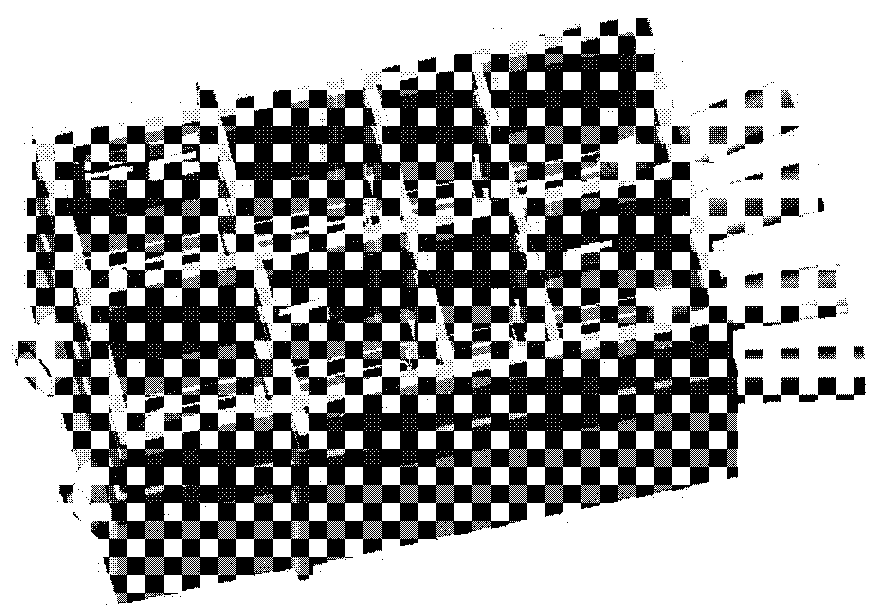
[0066] 2.1. The role of rough grid technology:

[0067] Physical sewage treatment is the use of physical action to separate suspended solid pollutants in sewage, and is the basic method of sewage treatment. Domestic sewage and industrial wastewater contain a...


PUM

PropertyMeasurementUnit
thicknessaaaaaaaaaa
widthaaaaaaaaaa
thicknessaaaaaaaaaa

Abstract

The invention relates to the technical field of underground project structures, in particular to a coarse grid sunk well for physically processing waste water and a construction method thereof. The coarse grid sunk well is a cavity structure which is formed by three layers of reinforced concrete structures. The structure of the first layer is a trapezoid, the left side and the right side of the trapezoid are provided with a plurality of connection pipelines, the upper part of the trapezoid is provided with a corresponding rectangular structure of the second layer, and the upper part of the rectangular structure of the second layer is provided with a corresponding rectangular structure of the third layer. The middle part of the coarse grid sunk well is provided with a horizontal partition, the coarse grid sunk well is divided into two groups of tank bodies through the partition, and the groups of the tank bodies are independently operated. Eight small lattices are arranged in the coarse grid sunk well, the sizes of the eight small lattices are different, and the gravity is offset. The construction method of the coarse grid sunk well comprises a step of preparing at early stage and a step of respectively constructing the three layers in batches. The invention has a simple and firm structure and wide application range, does not need arranging guide pipes and guide pipe platforms, does not need divers to work underwater, has visual concrete casting, controls the quality, saves the investment, improves the efficiency and reduces the risks.

Description

[Technical Field] [0001] The invention relates to the technical field of underground engineering structures, in particular to a coarse grid caisson used for physical treatment of sewage and a construction method thereof. [Background technique] [0002] Physical sewage treatment is the use of physical action to separate suspended solid pollutants in sewage, and is the basic method of sewage treatment. Domestic sewage and industrial wastewater contain a large amount of floating matter and suspended matter, and the treatment object of sewage treatment method is these floating matter and suspended matter. The function of the coarse grille: intercept large suspended or floating objects, reduce the load of the subsequent treatment structures, and protect the subsequent treatment structures or several groups of pumps. [0003] In the construction of underground caisson engineering, when the subsidence depth is large and groundwater is abundant, undrained subsidence combined with u...

Claims


Application Information

Patent Timeline
Patent Type & Authority Applications(China)
IPC IPC(8): B01D35/00E02D23/00E02D23/08
Inventor 曹国安张海涛宋芊严从林王靖
Owner 中铁市政环境建设有限公司
Why Eureka
Try Eureka