Supercharge Your Innovation With Domain-Expert AI Agents!

Tube expander

A tube expander and cylindrical body technology, applied in the field of tube expanders, can solve the problems of difficult coiling, limited range of applicable tube diameters, short life, etc., and achieve increased rotation flexibility, reliable production quality, and high production efficiency. Effect

Inactive Publication Date: 2013-09-25
信阳市四通机械制造有限公司
View PDF6 Cites 0 Cited by
  • Summary
  • Abstract
  • Description
  • Claims
  • Application Information

AI Technical Summary

Problems solved by technology

[0002] Expansion pipe is an important pipe used in the processing technology of expanded perlite. Due to the long body and large diameter of the expansion pipe, there is no ready-made mature product on the market; the existing expansion pipe is rolled by a pipe coiler. Formed, but due to the high strength of stainless steel, it is very difficult to roll. Every time before rolling the tube, the end of the steel plate needs to be pre-bent manually, so that the roundness and straightness of the rolled product have large errors. The roundness error is generally 6mm, and the straightness error is generally 10mm; due to the large errors of these two items, it is difficult to install the expansion furnace and the sealing performance around the expansion tube is poor; usually, after the expansion tube is rolled and welded, it needs to be expanded. The pipe device corrects the straightness and roundness of the pipe. However, the expanding roller of the existing pipe expanding device is fixed, which is easy to wear and has a short life. When in use, it is easy to cause damage to the expanding pipe. The angle cannot be adjusted, so that its applicable pipe diameter range is limited

Method used


Image

  • Tube expander
  • Tube expander
  • Tube expander

Examples


Embodiment Construction

[0020] The technical solutions of the present invention will be described in further detail below through specific embodiments.

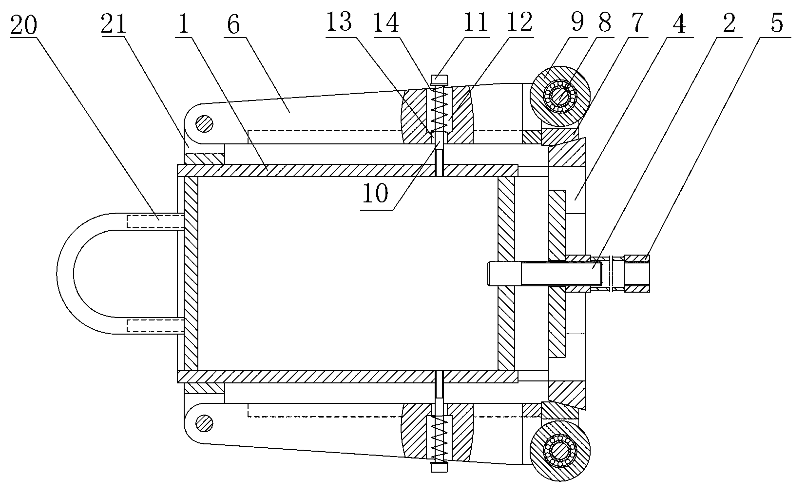
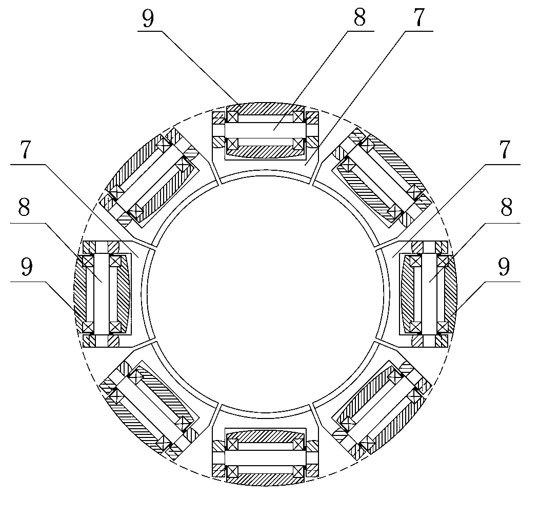
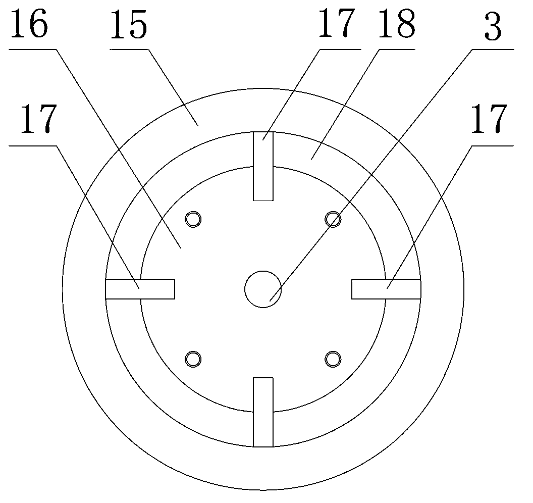
[0021] Such as figure 1 , figure 2 , image 3 , Figure 4 , Figure 5 , Image 6 with Figure 7 As shown, a tube expander includes a cylinder 1, eight groups of expanding roller structures evenly distributed on the outer surface of the cylinder 1, a lead screw 2, a cone 4 with a screw sleeve hole 3 in the center and Lead screw sleeve 5.

[0022] Wherein, the roller structure includes a swing arm 6, a roller frame 7 whose rear end is fixed to one end of the swing arm 6, a roller shaft 8 installed on the left and right side walls of the roller frame 7, and installed through bearings. The expanding roller 9 on the roller shaft 8; the expanding roller 9 is made of high-quality alloy steel and quenched.

[0023] Eight groups of swing arm seats 21 are fixed at the end of the cylinder body 1, and the eight groups of swing arm seats 21 are evenly d...


PUM


Abstract

The invention relates to a tube expander. The tube expander comprises a cylinder, eight groups of expanding roll structures, a leading screw, a conical plate and a leading screw sleeve, wherein each expanding roll structure comprises a swinging arm, an expanding roll framework of which a back end part is fixed to one end of the swinging arm, roll shafts which are installed on a left side wall and a right side wall of the expanding roll framework, and expanding rolls which are installed on the roll shafts through bearings; the other end of the swinging arm is hinged with the tail end of the cylinder; the expanding roll framework is arranged on the front part of the cylinder; the inner end of the leading screw is fixed inside the cylinder; the leading screw is parallel to an axial center line of the cylinder; an outer end part of the leading screw extends out of a cylinder opening at the front end of the cylinder; the conical plate is sleeved on the leading screw; the leading screw sleeve is installed on the leading screw; the conical plate is arranged between the expanding roll framework and the leading screw sleeve; the side surface of an excircle of the conical plate is a conical surface; a conical fan-shaped camber which is matched with the conical surface is arranged on a front end part of the bottom surface of the expanding roll framework; and the conical surface of the conical plate is arranged correspondingly to the conical fan-shaped camber of the expanding roll framework. The tube expander has the advantages of scientific design, high practicality, high production efficiency and reliable production quality.

Description

technical field [0001] The invention relates to equipment for processing pipes, in particular to a pipe expander for processing pipes. Background technique [0002] Expansion pipe is an important pipe used in the processing technology of expanded perlite. Due to the long body and large diameter of the expansion pipe, there is no ready-made mature product on the market; the existing expansion pipe is rolled by a pipe coiler. Formed, but due to the high strength of stainless steel, it is very difficult to roll. Every time before rolling the tube, the end of the steel plate needs to be pre-bent manually, so that the roundness and straightness of the rolled product have large errors. The roundness error is generally 6mm, and the straightness error is generally 10mm; due to the large errors of these two items, it is difficult to install the expansion furnace and the sealing performance around the expansion tube is poor; usually, after the expansion tube is rolled and welded, it n...

Claims


Application Information

Patent Timeline
Patent Type & Authority Patents(China)
IPC IPC(8): B21D39/08B21D3/02
Inventor 徐正明马国伟王元领贾志伟魏泽斌程志明
Owner 信阳市四通机械制造有限公司
Features
  • R&D
  • Intellectual Property
  • Life Sciences
  • Materials
  • Tech Scout
  • Unparalleled Data Quality
  • Higher Quality Content
  • 60% Fewer Hallucinations
Learn More