Workpiece drilling clamp

A technology for drilling jigs and workpieces, which is applied in the direction of drilling molds for workpieces, manufacturing tools, metal processing machinery parts, etc., and can solve the problems of inability to guarantee the position and size of holes, low repeat positioning accuracy, and low processing efficiency. Achieve the effects of simple structure, adaptability to mass production, and simple clamping

Inactive Publication Date: 2012-05-02
SANY HEAVY IND CO LTD (CN)
View PDF4 Cites 21 Cited by
  • Summary
  • Abstract
  • Description
  • Claims
  • Application Information

AI Technical Summary

Problems solved by technology

This processing method has the following deficiencies: 1) Using pads for positioning, the repeated positioning accuracy is low, and each clamping must be aligned; 2) The position of the hole is determined by scribing, and the position and size of the hole cannot be guaranteed; 3) It needs to go through four times of clamping, which takes a long time for clamping and low processing efficiency

Method used


Image

  • Workpiece drilling clamp
  • Workpiece drilling clamp
  • Workpiece drilling clamp

Examples


Embodiment 1

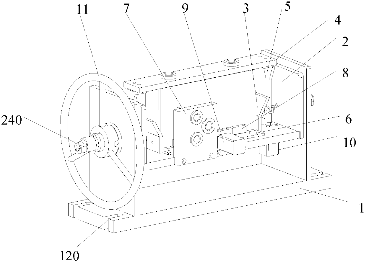
[0031] see figure 2 , figure 2 Schematic diagram of the fixture structure for the workpiece drilling.

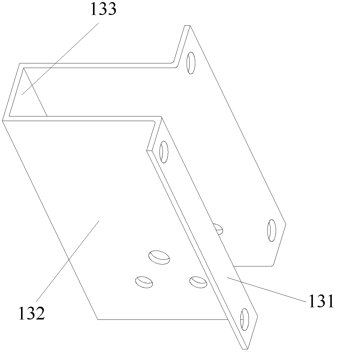
[0032] This embodiment proposes a workpiece drilling jig, which includes a base 1 , a rotating support 2 , a positioning mechanism 3 , a clamping mechanism 8 and two first fixed drilling templates 7 . The base 1 includes a first bottom plate 140 , a first side plate 120 and a second side plate 130 , and the first side plate 120 and the second side plate 130 are fixedly connected to the first bottom plate 140 respectively. The rotating support 2 includes a second bottom plate 260 , a third side plate 250 and a fourth side plate 270 , and the third side plate 250 and the fourth side plate 270 are fixedly connected to the second bottom plate 260 respectively. The rotating support 2 is disposed in the base 1 , and the first side plate 120 is rotatably connected to the third side plate 250 , and the second side plate 130 is rotatably connected to the fourth side plate 270 . ...

Embodiment 2

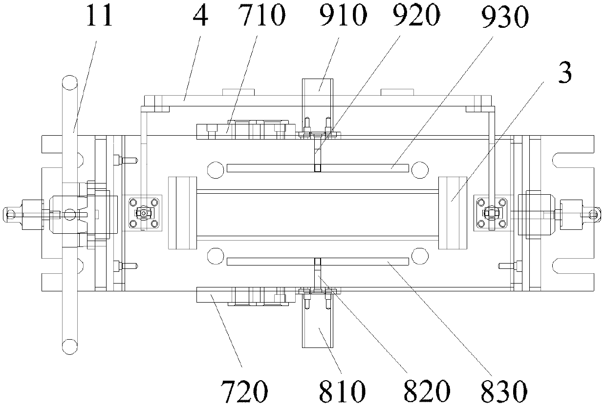
[0038] see Figure 5 , Figure 5 Schematic diagram of the positioning mechanism.

[0039] This embodiment is further improved on the basis of the first embodiment: the positioning mechanism 3 includes a positioning plate 330 , a positioning seat 320 and two baffles 310 . The positioning plate 330 is fixedly connected to the upper surface of the second bottom plate 260 , the positioning seat 320 is connected to the upper surface of the positioning plate 330 , and the two baffles 310 are respectively connected to two ends of the fixing seat 320 .

[0040] In practice, the positioning seat 320 is a wedge-shaped structure, and the upper part of the baffle plate 310 is set as a certain inclined surface, which facilitates the installation of the workpiece.

[0041] Between the positioning plate 330 and the second bottom plate 260 , between the positioning seat 320 and the positioning plate 330 , and between the baffle plate 310 and the positioning seat 320 can be fixed connections...

Embodiment 3

[0044] This embodiment is further improved on the basis of the first or second embodiment: it also includes an indexing hand wheel 11 .

[0045] see Figure 4 , the base 1 is rotationally connected with the swivel support 2. The first side plate 120 on the base 1 and the third side plate 250 on the swivel support 2 are rotatably connected through the mandrel 210, and the second side plate 130 on the base 2 is connected to the fourth side plate 270 on the swivel support 2 through The mandrel 210 is rotatably connected, and the specific connection relationship is: the mandrel 210 is fixedly connected with the third side plate 250 or the fourth side plate 270, and shaft holes are arranged on the first side plate 120 and the second side plate 130, and the mandrel 210 The bearing 220 is connected with the shaft hole, and a bearing cover 230 is arranged outside the shaft hole. The indexing handwheel 11 is connected with one of the mandrels 210 , and the rotating support 2 is drive...


PUM


Abstract

The invention provides a workpiece drilling clamp, which comprises a base, a rotation support, a positioning mechanism, a clamping mechanism and two first drilling templates, wherein the base comprises a first base plate, a first side plate and a second side plate, and the first side plate and the second side plate are fixedly connected with the first base plate; the rotation support comprises a second base plate, a third side plate and a fourth side plate, and the third side plate and the fourth are fixedly connected with the second base plate; the rotation support is arrange inside the base, the first side plate is in rotating connection with the third side plate, and the second side plate is in rotating connection with the fourth side plate; the positioning mechanism is fixedly connected to the second base plate; the clamping mechanism comprises a first clamping mechanism and a second clamping mechanism, which are respectively arranged at both sides of the positioning mechanism; and the two first drilling templates are respectively arranged at both sides of the positioning mechanism and fixedly connected with the second base plate. The workpiece drilling clamp provided by the invention has the advantages of simple structure, convenience in assembling and clamping and high processing precision and automation degree, can greatly improve product assembly efficiency, and is suitable for volume-production.

Description

technical field [0001] The invention relates to a fixture, in particular to a workpiece drilling fixture. Background technique [0002] The belt conveyor tensioning support is a several-shaped workpiece, which is an important part of the belt conveyor of the mixing station. Its machining quality has a very important influence on the subsequent assembly quality and the tensioning effect of the belt conveyor belt. The shape of the tensioning support of the belt conveyor is as follows: figure 1 As shown, it is a formed part. The four sides of the workpiece need to be drilled to form a space dimension. The traditional drilling method first marks the line, uses the spacer to support the tooling, and then clamps the workpiece with the pressure plate. For the machining of the radial arm drill, each surface of the drill needs to be clamped and aligned once. This processing method has the following deficiencies: 1) Using pads for positioning, the repeated positioning accuracy is l...

Claims


Application Information

Patent Timeline
Patent Type & Authority Applications(China)
IPC IPC(8): B23Q3/00B23B47/28
Inventor 郑明辉郑强蔡鑫
Owner SANY HEAVY IND CO LTD (CN)
Why Eureka
Try Eureka