Novel electrifying way and device for bucket wheel machine

A bucket wheel machine and cable technology, applied in the direction of transportation, packaging, loading/unloading, etc., can solve the problems of large torsion angle and stretching length of cables, affecting material flow capacity, and unsatisfactory rotation on the line, etc., to achieve system optimization, Save control cables and installation costs and increase maintenance costs

Active Publication Date: 2012-05-02
HUNAN CHANGZHONG MACHINERY
View PDF6 Cites 2 Cited by
  • Summary
  • Abstract
  • Description
  • Claims
  • Application Information

AI Technical Summary

Problems solved by technology

There are three disadvantages in the traditional rotary on-line method: First, there are central hoppers on the door seat of the bucket wheel stacker and reclaimer and the middle of the rotary platform, and materials pass through the hopper. In order to prevent the cables from being damaged by materials, there should be steel pipes on the outside of the cable on the center line. Protection, the steel pipe in the center of the hopper greatly affects the flow capacity of materials passing through the hopper, and is prone to material blocking; second, when the rotation angle is large, the torsion angle and stretching length of the cable are large, and the cable is prone to fatigue damage; It is the twisting movement of the cable in the steel pipe, and the cable has a certain amount of friction with the inner wall of the steel pipe. After a long working time, the cable will be worn out. Therefore, the traditional center on-line device is not ideal for the rotary on-line of the bucket wheel stacker and reclaimer with a large rotation angle.

Method used


Image

  • Novel electrifying way and device for bucket wheel machine
  • Novel electrifying way and device for bucket wheel machine
  • Novel electrifying way and device for bucket wheel machine

Examples


Embodiment Construction

[0023]The present invention will be described in further detail below in conjunction with accompanying drawing and embodiment, embodiment is intended to illustrate the present invention rather than to the further limitation of the present invention, as not departing from the design spirit of the present invention, those of ordinary skill in the art make various solutions to the present invention Deformation, improvement, and retouching all fall within the scope defined by the claims of the present invention.

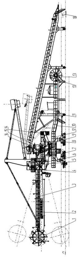
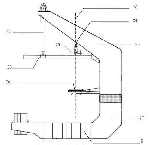
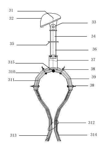
[0024] The following is only one of the exemplary embodiments, such as figure 1 , figure 2 , image 3 As shown, a bucket wheel machine with a fixed single-tail car or trailer structure consists of a bucket wheel mechanism (1), a front arm frame (2), an arm frame belt conveyor (3), a cab (4), and an upper structure parts (5), pitching mechanism (6), traveling trolley (7), door seat (8), slewing mechanism (9), tail car (10), electrical (11), lubrication system (12), wa...


PUM


Abstract

The invention relates to a novel electrifying way and device for a bucket wheel machine. A conductor line is selected preferably for supplying power to the bucket wheel machine; a collector brush on a current collector at the bottom end of a machine body is in sliding contact with a guide rail; electric energy is directly conducted to a walking system; the current collector of a conductor line system is electrically connected with the walking system through a cable; the walking system is used for controlling a part of lines to enter an auxiliary control room on a trailer; a communication linegetting out of the auxiliary control room reaches upwards to an electrifying device on the revolving central line of an upright post through a trailer main beam together with power lines of a bucket wheel, a belt feeder, a revolving mechanism and a pitching system; the power lines of the bucket wheel, the belt feeder, a revolving mechanism and the pitching system and a communication line between the auxiliary control room and a driving cab pass through the electrifying device; a communication line which gets out of the electrifying device and is used for connected the auxiliary control room with the driving cab directly enters the driving cab; a power wire getting out of the electrifying device is introduced into the bucket wheel, the belt feeder, the revolving mechanism and the pitching system for supplying power respectively; and communication lines of these parts get back to the driving cab.

Description

technical field [0001] The invention relates to a bucket wheel machine, in particular to a new on-line mode and device of a bucket wheel stacker and reclaimer, belonging to the field of bulk material stacking and reclaiming equipment in operation transportation. Background technique [0002] Bucket Wheel Conveyor is a large-scale bulk material conveying equipment widely used in ports, electric power, coal, metallurgy and other industries. It is divided into stacker and reclaimer according to its function. According to the form of the running device, the bucket wheel machine can be divided into: crawler type, tire type and track type, among which the track type is the most widely used structural form at present. Take the material. [0003] There are two power supply methods for bucket wheel machines: cable power supply and trolley line power supply; bucket wheel machine cables are divided into power cables for power supply and communication cables for control. During the ope...

Claims


Application Information

Patent Timeline
Patent Type & Authority Applications(China)
IPC IPC(8): B65G65/04B65G65/28
Inventor 万正喜易春光彭高明黄志刚许晓奇
Owner HUNAN CHANGZHONG MACHINERY
Why Eureka
Try Eureka