Eureka AIR delivers breakthrough ideas for toughest innovation challenges, trusted by R&D personnel around the world.

Tunnel bottom concrete side-slipping lining construction method and side-slipping needle beam bottom board trolley

A construction method and concrete technology, which are applied in tunnel lining, wellbore lining, earth-moving drilling, etc., can solve problems such as defects in the appearance of air bubbles, inability to discharge air bubbles in time, and temperature cracks when new and old concrete are overlapped on different platforms. Social benefits, the effect of reducing bubble defects and improving construction conditions

Inactive Publication Date: 2012-05-02
广汉金达隧道机械有限公司
View PDF11 Cites 16 Cited by
  • Summary
  • Abstract
  • Description
  • Claims
  • Application Information

AI Technical Summary

Problems solved by technology

Although the hydraulic system is used for mold erection and demoulding, with high automation and high work efficiency, due to the limitation of construction conditions on the forming surface, the air bubbles cannot be discharged in time when the concrete is vibrated, and there will always be a large number of air bubbles on the bottom concrete surface, which may cause appearance quality defects. Quality problems such as lapping of new and old concrete, temperature cracks, etc., are only suitable for tunnel construction with small height difference of lining concrete

Method used


Image

  • Tunnel bottom concrete side-slipping lining construction method and side-slipping needle beam bottom board trolley
  • Tunnel bottom concrete side-slipping lining construction method and side-slipping needle beam bottom board trolley
  • Tunnel bottom concrete side-slipping lining construction method and side-slipping needle beam bottom board trolley

Examples


Embodiment

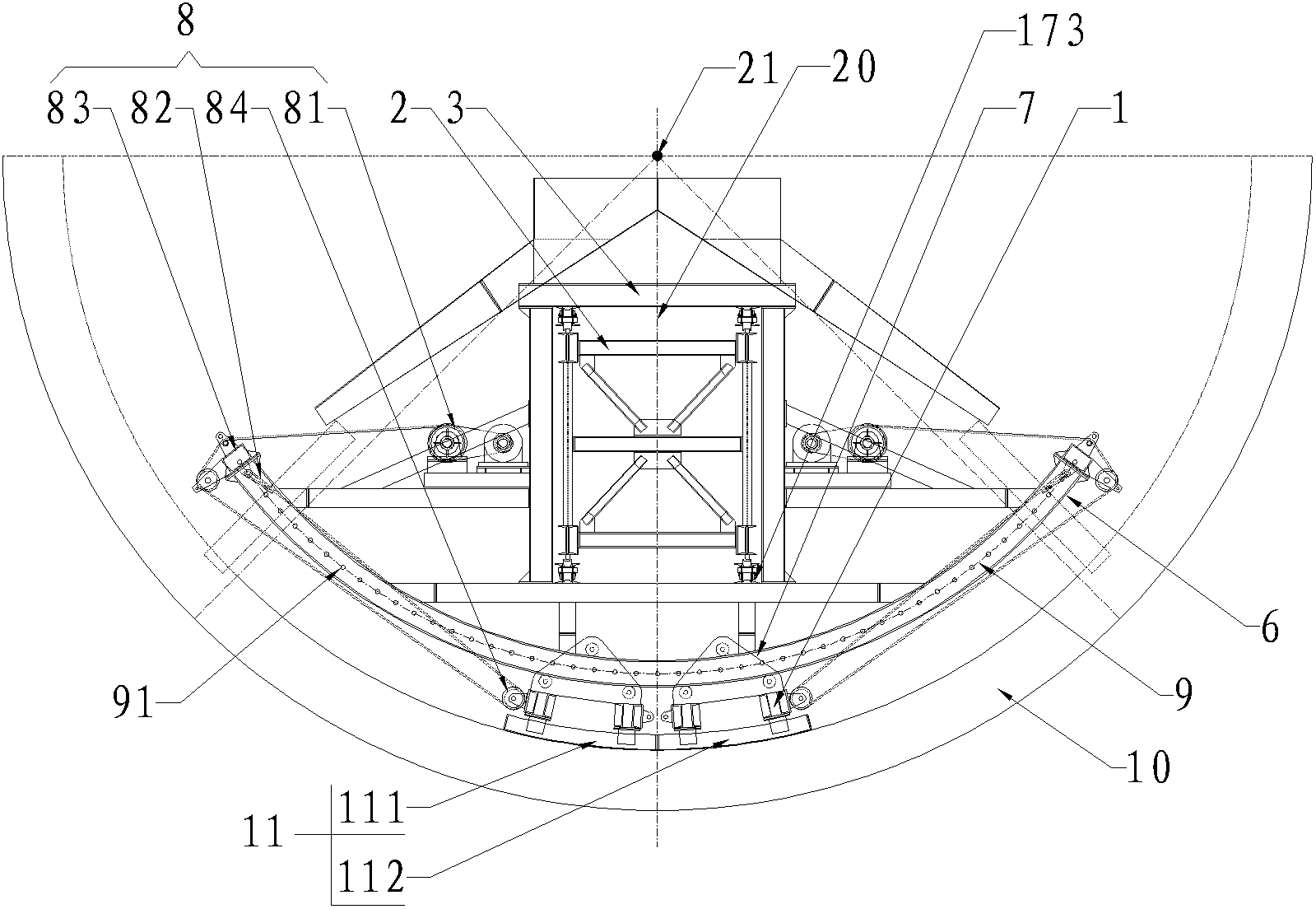
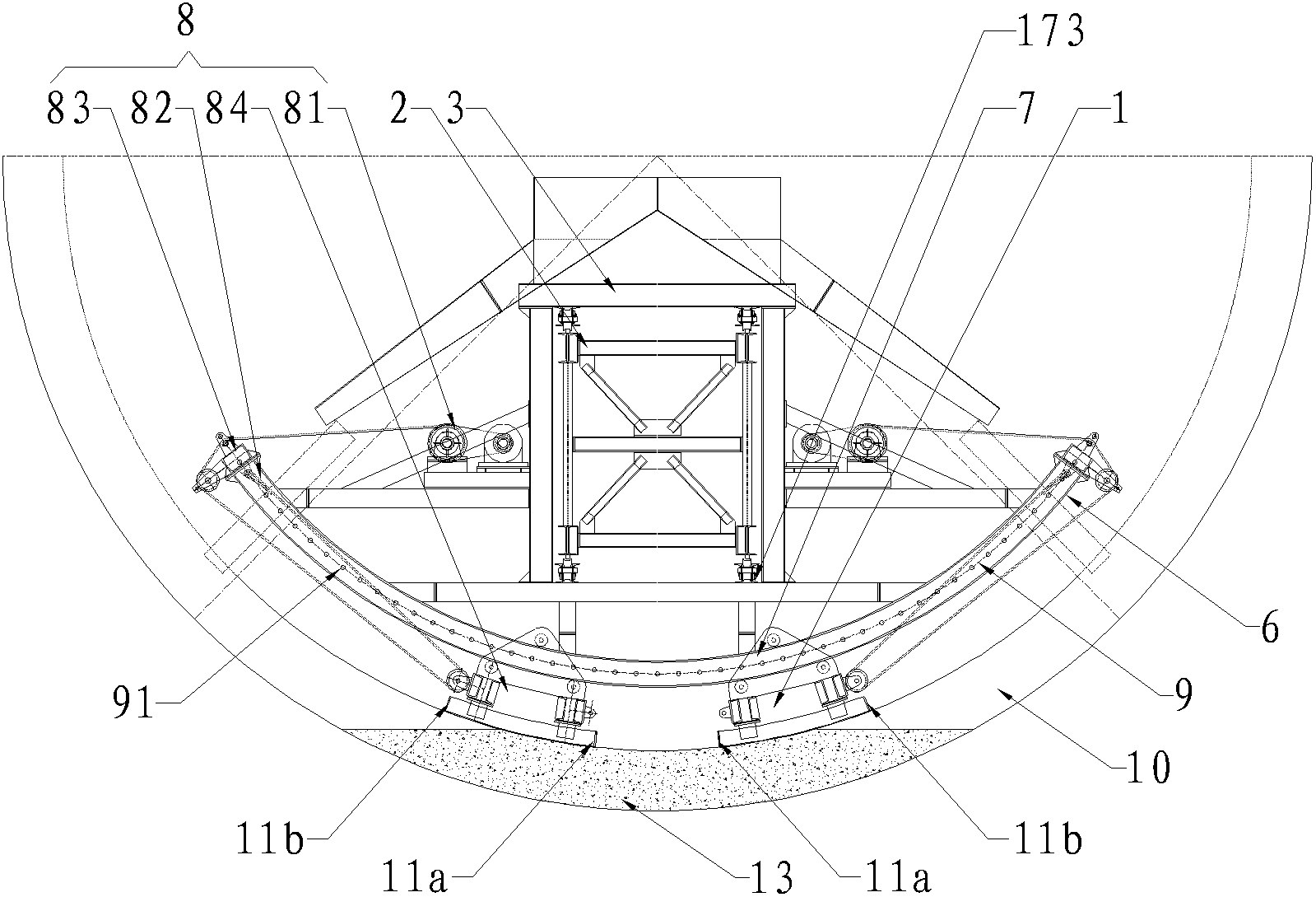
[0054] A side-sliding needle beam bottom mold trolley is mainly composed of formwork assembly 1, guide rail 6, side-slip traction system 8, beam frame assembly 3, needle beam assembly 2, walking system 17, guide slide mechanism 7, centering Adjusting device 16, hydraulic system 18, electrical system 19 and other components.

[0055] Its every cover template comprises left and right two slide templates 11. The outer contour size of the formwork is designed according to the tunnel forming radius. The width of each sliding formwork 11 is generally designed to be 1-1.5 meters, and the longitudinal length of the two sliding formworks 11 is designed according to the tunnel construction requirements. The single-sided sliding formwork 111 and 112 are connected by two double-channel steel combined steel beams to ensure that the entire formwork has sufficient rigidity and straightness. Considering the convenience of transportation and hoisting, the shaped steel beams and formwork are d...


PUM


Abstract

The invention discloses a tunnel bottom concrete side-slipping lining construction method capable of overcoming the bubble defect and a side-slipping needle beam bottom board trolley. The method sequentially comprises construction steps of in-position of a formwork group, side-slipping pouring of concrete and longitudinal movement of the trolley. Guiding tracks matched with designed linear dimension of a tunnel construction face are respectively and fixedly connected in front of and on the back of the lower portion of a beam frame assembly of the side-slipping needle beam bottom board trolley. The formwork group consists of a pair of slide formworks, the pair of slide formworks is symmetrical with a vertical face where the central line of a beam frame is located and is respectively connected with the guiding tracks through a sliding guide mechanism, and the sliding guide mechanism is connected with the beam frame assembly through a side-slipping traction system. The tunnel bottom concrete side-slipping lining construction method is capable of overcoming the defects of bubbles on the surface of concrete, overlap-joint slab staggering of new and old concrete, temperature cracking and the like, has the advantages of being reliable in structure, quick in lining speed, good in construction quality and safe in construction, reducing interference of construction conditions and the like, and is mainly used for side-slipping lining construction of tunnel bottom concrete.

Description

technical field [0001] The invention relates to a tunnel concrete construction method and device, in particular to a tunnel bottom concrete lining construction method and device. Background technique [0002] At present, the concrete lining construction at the bottom of circular tunnels generally adopts three construction methods: combined small formwork, drag formwork and needle beam bottom formwork lining. The so-called circular tunnel bottom concrete generally refers to the center of the arc corresponding to the arc length The angle is 90° or 120°. [0003] First, combined small formwork construction. This method uses standard small formwork for combined construction, mainly relying on a large amount of manual labor to set up the formwork, concrete pouring, and demoulding. A section refers to a section of lining section corresponding to the longitudinal length of the formwork. After the construction of a section, the formwork is manually moved. Go to the next section fo...

Claims


Application Information

Patent Timeline
Patent Type & Authority Applications(China)
IPC IPC(8): E21D11/10
Inventor 杨党荣周平刘仲伟
Owner 广汉金达隧道机械有限公司
Why Eureka
Eureka Blog
Learn More