Crushing pump utilizing streamlined cutter heads

A streamlined, pulverized pump technology, applied to parts, pumps, pump elements, etc. of pumping devices used for elastic fluids, can solve problems such as cavitation of the cutter head, improper shape of the cutter head, flow disorder at the inlet of the crushed pump, etc. , to achieve the effect of reducing hydraulic loss and improving performance

Inactive Publication Date: 2012-05-02
JIANGSU GUOQUAN PUMP MFG CO LTD
View PDF8 Cites 4 Cited by
  • Summary
  • Abstract
  • Description
  • Claims
  • Application Information

AI Technical Summary

Problems solved by technology

For the traditional crushing pump, because there is a cutter head at the inlet of the pump, the shape of the cutter head is improper, the flow at the inlet of the crushing pump is relatively turbulent, and cavitation will occur near the rotating cutter head, resulting in the lift, flow and Efficiency and other aspects of performance decline

Method used


Image

  • Crushing pump utilizing streamlined cutter heads
  • Crushing pump utilizing streamlined cutter heads
  • Crushing pump utilizing streamlined cutter heads

Examples


Embodiment Construction

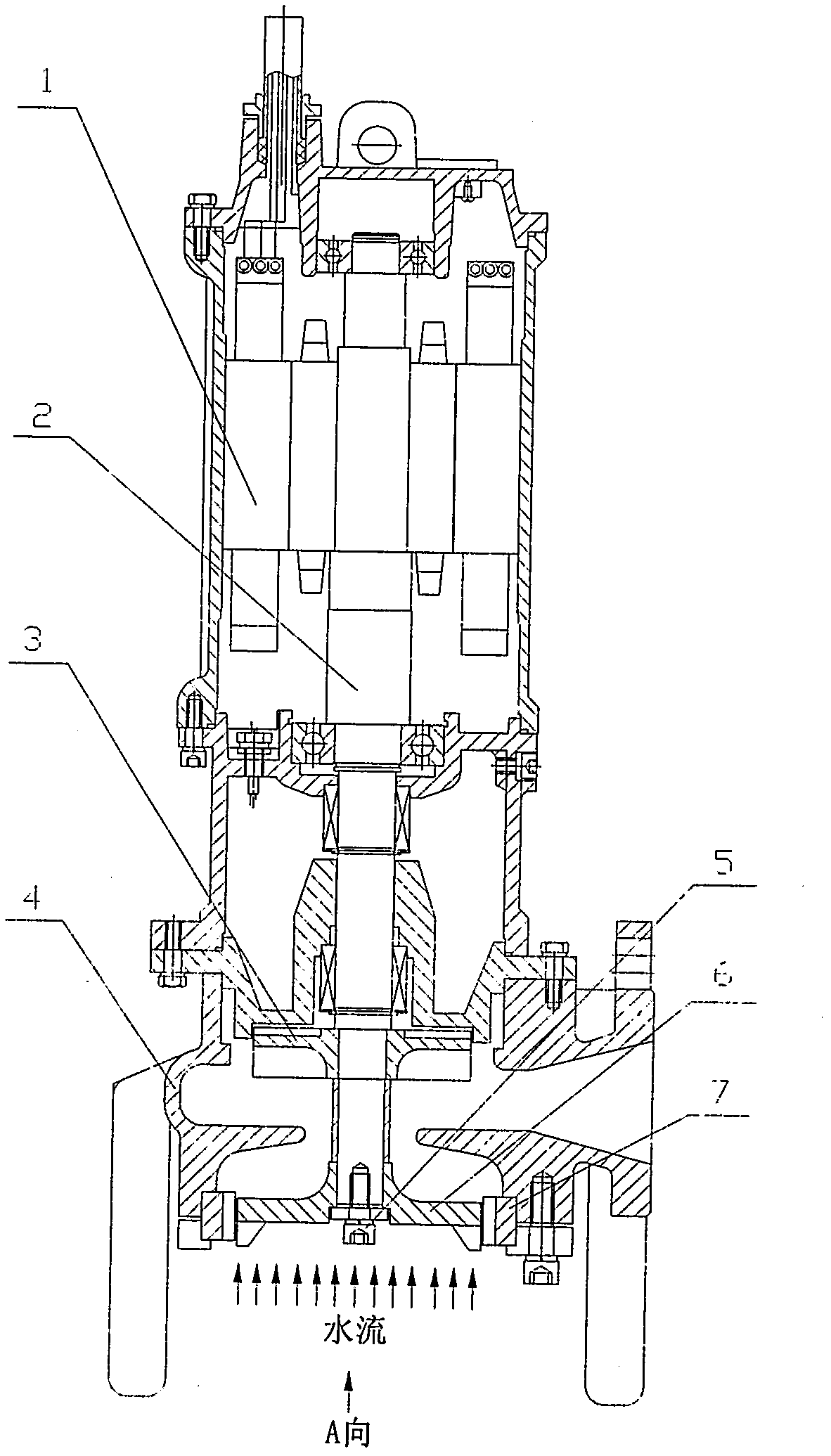
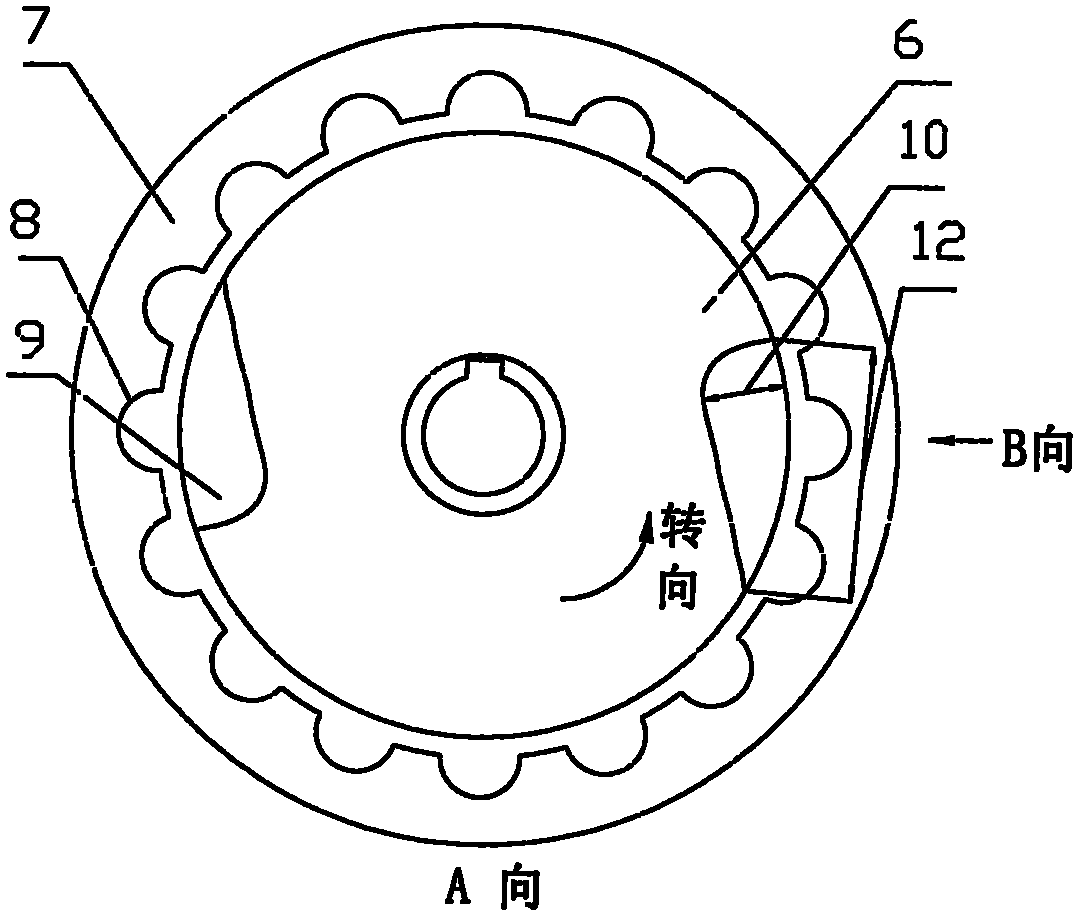
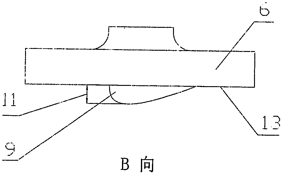
[0012] figure 1 , figure 2 and image 3 Determined to adopt the structural form of the streamline cutter head pulverizing pump in the present embodiment jointly, it is by motor (1), shaft (2), impeller (3), pump body (4), fastening bolt (5), movable cutterhead (6), static cutter head (7), semicircular runner (8), cutter head (9), cutter head width B (10), cutter head height H (11), cutter head length L (12), The lower surface of the cutter head (13) is composed of a crushing device installed before the inlet of the impeller (3), and the crushing device is mainly composed of two parts: the moving cutter head (6) and the static cutter head (7); the moving cutter head (6) Fix the shaft end before the inlet of the impeller (3), press the fastening bolt (5) on the shaft end to fix it axially on the shaft (2), and the movable cutter head (6) rotates with the shaft (2), On the lower surface (13) of the movable cutterhead (6), there is no less than one cutter head (9) near the out...


PUM


Abstract

The invention relates to a crushing pump utilizing streamlined cutter heads. A crushing device is installed in front of an impeller inlet and substantially comprises a dynamic cutter and a static cutter. The dynamic cutter is fixed at the shaft end in front of the impeller inlet and pressed on the shaft through a fastening bolt of the shaft end to achieve axial fixing. The dynamic cutter rotates along with a pump shaft. More than one cutter head is arranged on the lower surface of the dynamic cutter close to the position of the external diameter and downwards extend for a certain height along the shaft. The cutter heads are in streamlined shapes viewed both from the axial direction and the radial direction. The cutter heads are in streamlined shapes with both the width and the height decreasing in the direction opposite to the rotating direction. The static cutter is fixed on fixed pieces such as a pump body, a pump cover or the like, a plurality of semi-circular flow channels for limiting the diameter of particles passing through are arranged on the inner circumference of the static cutter, and two sides of each flow channel form two cutting edges matched with the rotating cutter heads of the dynamic cutter to crush sundries. The dynamic cutter utilizes the streamlined cutter heads, thereby reducing flow losses and effectively improving flow situations of the inlet of the crushing pump and crushing performance of the crushing pump.

Description

technical field [0001] The invention relates to a pulverizing pump, in particular to a pulverizing pump adopting a streamlined cutter head. Background technique [0002] The pulverizer pump is a non-clog pump used to transport sewage. The large particles and long-fiber debris in the sewage enter the crushing pump, and are first crushed by the cutter head at the inlet, and then transported out by the pump. For the traditional crushing pump, because there is a cutter head at the inlet of the pump, the shape of the cutter head is improper, the flow at the inlet of the crushing pump is relatively turbulent, and cavitation will occur near the rotating cutter head, resulting in the lift, flow and Efficiency and other aspects of performance decline. Therefore, it is necessary to change the shape of the cutter head, reduce the flow resistance, improve the flow condition at the inlet of the crushing pump, and then improve the performance of the crushing pump. Contents of the inve...

Claims


Application Information

Patent Timeline
Patent Type & Authority Applications(China)
IPC IPC(8): F04D29/00B02C18/10B02C18/18
Inventor 朱荣生杨爱玲
Owner JIANGSU GUOQUAN PUMP MFG CO LTD
Why Eureka
Try Eureka